39
motor rotating circle
is 10000.
a)
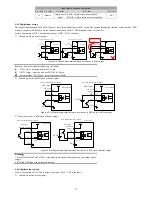
If P1-27 = 10, P1-28=1, the motor rotates one circle with 1000 external pulse input
b)
If the P1-27=1, P1-28=10, the motor rotates one circle with 100000 external pulse input
5)
Enable drive. Keep DI1 and COM which are in the CN4 terminal short connected, the drive will enable (DI1is the default servo enable
terminal, the user can modify it by function code).
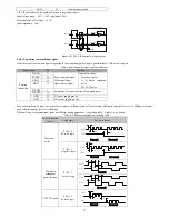
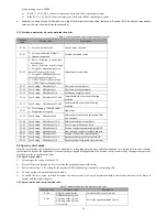
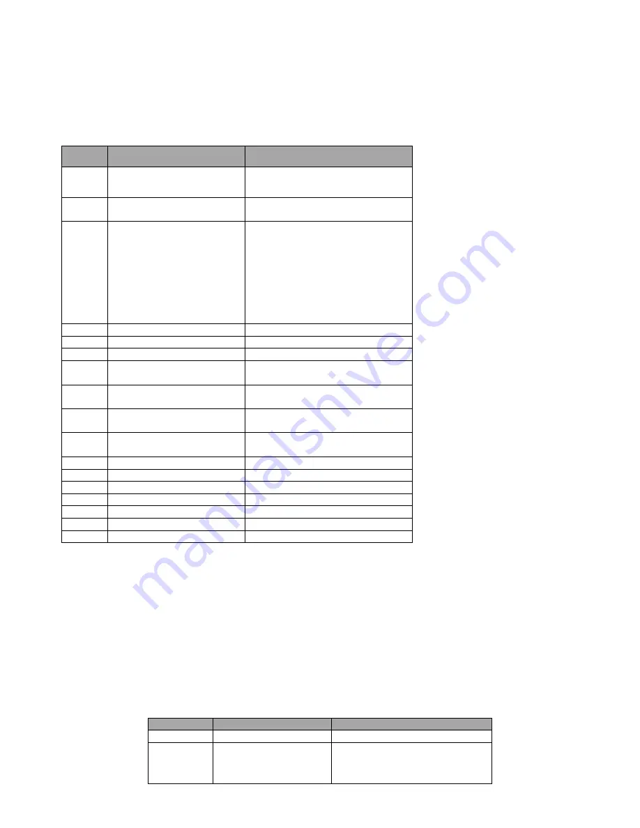
5.3.3 Position control mode when the main function code
Table 5-1 Main function code for position control mode
Function
code
Setting value
Description
P1-00
1
:
Position control mode
Control mode selection
P1-01
0
:
External command (Default)
1
:
Internal instruction
Position command source
P1-02
0
:
Pulse + direction
,
positive logic
(
default value
)
1
:
Pulse + direction
,
negative logic
2
:
Two phase orthogonal pulse (4
times of frequency), positive
3
:
Two phase orthogonal pulse (4
times of frequency), negative
4
:
CCW/CW pulse, positive logic
5
:
CCW/CW pulse, negative logic
External pulse input form
P1-27
User Setting
,
Default value 1
Electronic gear molecular
P1-28
User Setting
,
Default value 1
Electronic gear denominator
P1-33
User Setting
,
Default value 10
Positioning complete width
P1-36
User Setting
,
Default value 25000
Alarm threshold of position following
deviation
P1-37
User Setting
,
Default value 25000
Fault threshold of position following
deviation
P1-53
0
:
Free stopping
(
Default value
)
1
:
Stopping at zero speed
Stop mode
P1-15
User Setting
,
Default value 0
External pulse instruction smoothing filter
time constant
P1-46
User Setting
,
Default value 300
Forward maximum torque limit
P1-47
User Setting
,
Default value 300
Reverse maximum torque limit
P5-00
User Setting
,
Default value 30
Position regulator proportional gain KPP
P5-02
User Setting
,
Default value 0
Front position regulator feedforward gain
P5-03
User Setting
,
Default value 5
Position feedforward smoothing time
P5-04
User Setting
,
Default value 350
Speed regulator proportional gain KVP
P5-05
User Setting
,
Default value 10
Speed regulator integration time constant
5.4 Speed control mode
In speed control mode, the rotational speed is controlled by analog input, digital input, and communication. It is mainly used in some constant
speed situation. Such as the application of the analog engraving and milling machine, the position control is achieved by the upper computer, the
servo drive works in speed control mode.
5.4.1 Speed control mode:
1)
According to the wiring of section 3.10.
2)
Servo JOG test run through the key to confirm the normal operation of the motor.
3)
Refer to the section 3.10.2 wiring for the necessary DI/DO and analog terminals for connecting CN4.
4)
To carry out the relevant setting of speed mode.
5)
To enable the servo drive, and then first make the motor rotate at low speed, determine whether the rotation direction of the motor is
normal, and then adjust the gain.
5.4.2 Speed control mode main function code:
Speed control mode when the main function code
Function code
Reference value
Description
P1-00
0: Speed control mode
Control mode is speed control
P1-05
0: Internal digital given
1: Analog value 1 given
2: Analog value 2 given
3: Not used
Select the speed command source

