78
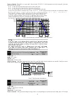
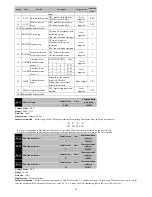
first order low pass filter model without a static error, transfer function
:
*
1
1
1
s
s
s
KPP
position loop response frequency
:
(
)
2
KPP
Hz
0
t
Instruction
position
63.2%
The actual
position
1/KPP Unit s
7-19 Position regulator proportional gain
The time required to reach 63.2% of a target position is the reciprocal of position regulator proportional gain.
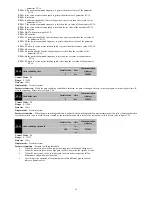
P5-01
Position regulator proportional gain
fluctuation ratio
Initail value
Unit
Communication
Address
50
%
2501H
Control Mode
:
P S
Range
:
10
~
500
Data size
:
16bit
Display mode
:
Decimal system
Parameter function
:
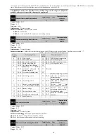
When the gain switching condition is satisfied, it‘s the rate of change for target position regulator proportional gain
.
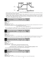
P5-02
Front position regulator feedforward
gain
Initail value
Unit
Communication
Address
0
%
2502H
Control Mode
:
P
Range
:
0.0
~
100.0
Data size
:
16bit
Display mode
:
Decimal system
Parameter function
:
Set front position regulator feed forward gain
When smooth change of position control command, increase this gain can reduce the position track deviation.
When position control instruction is not smooth change, reduce this gain can improve the resonance condition of mechanical operation.
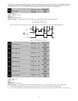
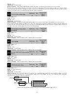
P5-03
Position feed forward smoothing
constant
Initail value
Unit
Communication
Address
5
ms
2503H
Control Mode
:
P
Range
:
2
~
100
Data size
:
16bit
Display mode
:
Decimal system
Parameter function
:
Set the first order filter time constant of feed forward gain of position regulator.
When smooth change of position control command, decrease this smoothing constant can improve the position track deviation.
When position control instruction is not smooth change, increase this smoothing constant can improve the resonance condition of
mechanical operation.
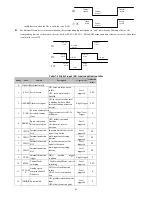
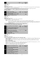
P5-04
Proportional gain of speed regulator
KVP
Initail value
Unit
Communicatio
n Address
350.0
rad/s
2504H
Control Mode
:
P S
Range
:
0.1
~
5000.0
Data size
:
16bit
Display mode
:
Decimal system
Parameter function
:
When the gain value of the speed control is increased, the speed of the response can be improved. It will produce vibration
and noise when it is too large.
This parameter determines the speed control loop response, the greater KVP set up the higher speed loop frequency response, the speed of the
instructions to follow the better, but it‘s easy to trigger a mechanical resonance when to set large. The response frequency of the speed loop must
4 ~ 6 times higher than the response frequency of the position loop, when the position response frequency is higher than speed response
frequency, the system may produce jitter or positioning will have overshoot phenomenon. The calculation of the response frequency of the speed
loop is as follows:
When the estimated or set P5-08 is equal to the true
/
JL JM
:


