62
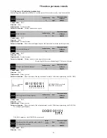
P1-06=2
:
External DI input switch operation by table 7-3. The DI terminal needs to set to 5 (CMD0), 6 (CMD1), 7 (CMD2) and 8 (CMD3)
function.
DI default is low level valid, if 4 input (5/6/7/8) DI form a 4bit number in the following ways:
D:
CMD0
CMD1
CMD2
CMD3
0
3
, thenD is 0000-1111 corresponding to pr1-pr16, system according to the value of D running at different
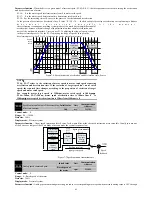
speed command spd. As shown in the following diagram.
CMD3
CMD2
CMD1
CMD0
Spd
Spd
1
Spd
2
Spd
3
Spd
4
Spd
5
Spd
6
Spd
7
Spd
8
Spd
9
Spd
10
Spd
11
Spd
12
Spd
13
Spd
14
Spd
15
Spd
16
Spd
1
NOTE:
1
:
It will not take effect that if modifies the current segment paraments in the operation when
P1-06=0 or1.
2
:
T h e s e g m e n t h a s i m p l e m e n t e d w i l l b e c l e a r e d t h a t i f c a n m a k e O F F o r p o w e r d o w n i n
the operation when P1-06=0 or 1.At the moment , if directly to run again, since Spd1 starts
execution.
3
:
I f D I t e r m i n a l s t a t e u n c h a n g e d , s e r v o d r i v e r u n c o n t i n u o u s l y a c c o r d i n g t o t h e c u r r e n t D I
t e r m i n a l s t a t e c o r r e s p o n d i n g s p e e d w h e n P 1 - 0 6 = 2 . O n c e t h e D I t e r m i n a l s t a t e c h a n g e s , t h e n
i m m e d i a t e l y r u n t o t h e s p e e d o f n e w D I t e r m i n a l s t a t e a c c o r d i n g t o a c c e l e r a t i o n a n d
deceleration time.
Table7-3 Internal multistage speed instruction
(
DI
)
function
Internal
speed
instruction
CMD3
CMD2 CMD1 CMD0
Corresponding
paramter
Explaination
Spd1
0
0
0
0
P3-00
Setting speed (0-±motor rated speed)
Spd2
0
0
0
1
P3-02
Setting speed (0-±motor rated speed)
Spd3
0
0
1
0
P3-04
Setting speed (0-±motor rated speed)
Spd4
0
0
1
1
P3-06
Setting speed (0-±motor rated speed)
Spd5
0
1
0
0
P3-08
Setting speed (0-±motor rated speed)
Spd6
0
1
0
1
P3-10
Setting speed (0-±motor rated speed)
Spd7
0
1
1
0
P3-12
Setting speed (0-±motor rated speed)
Spd8
0
1
1
1
P3-14
Setting speed (0-±motor rated speed)
Spd9
1
0
0
0
P3-16
Setting speed (0-±motor rated speed)
Spd10
1
0
0
1
P3-18
Setting speed (0-±motor rated speed)
Spd11
1
0
1
0
P3-20
Setting speed (0-±motor rated speed)
Spd12
1
0
1
1
P3-22
Setting speed (0-±motor rated speed)
Spd13
1
1
0
0
P3-24
Setting speed (0-±motor rated speed)
Spd14
1
1
0
1
P3-26
Setting speed (0-±motor rated speed)
Spd15
1
1
1
0
P3-28
Setting speed (0-±motor rated speed)
Spd16
1
1
1
1
P3-30
Setting speed (0-±motor rated speed)
NOTE: In the table, 0/1 is just respectively invalid/effective, doesn’t represent the actual
level. More are available at logic level settings
.
P1-07
Frequency dividing output
Initial value
Unit
Communication
Address
2500
ppr
2107H
Control mode
:
P S T
Range
:
When using 2500ppr encoder
:
358~2500
;
When using 17bit encoder
:
1171
~
4095
Data size
:
16bit
Display mode
:
Decimal system
Parameter function
:
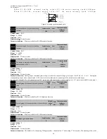
Servo motor rotation one circle, drive feedback A, B pulse number to the host computer.
For example, P1-07=550, then servo motor rotation one circle, PA+-
、
PB+- terminals output 550 pulse, the orthogonal relationship between
PA+- pulse and PB+- pulse.
Do not set the value beyond the above range, otherwise the output pulse will be incorrect.
P1-08
Torque command selection
Initial value
Unit
Communication
Address
0
-
2108H
Control mode
:
T
Range
:
0
~
2
Data size
:
16bit
Display mode
:
Decimal system
Parameter function
:
Select the source of the torque command on torque control mode
P1-08=0
:
Internal digital given (P4-00 given);


