67
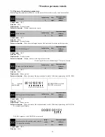
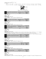
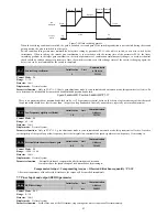
interpretation of the electronic gear.
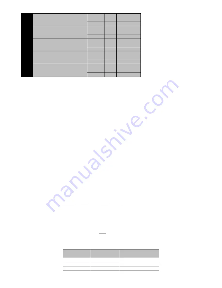
P1-27
Electronic gear numerator 1
Initail value
Unit
Communication
Address
1
-
211BH
P1-28
Electronic gear denominator
Initail value
Unit
Communication
Address
1
-
211CH
P1-29
Electronic gear numerator 2
Initail value
Unit
Communication
Address
1
-
211DH
P1-30
Electronic gear numerator 3
Initail value
Unit
Communication
Address
1
-
211EH
P1-31
Electronic gear numerator 4
Initail value
Unit
Communication
Address
1
-
211FH
Control Mode
:
P
Range
:
1~65535
Data size
:
16bit
Display mode
:
Decimal system
Parameter function
:
P1-26~P1-31used to set electronic gear ratio.
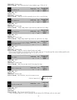
Electronic gear ratio
It can be easily match with all kinds of pulse source through setting electronic gear ratio under position control mode, in order to achieve the
ideal control resolution ( the Angle/pulse).
Electronic gear ratio set way
:
①
Set electronic gear ratio factor
P1-26
。
Set
electronic gear ratio factor
mainly depend on the type of the encoder motor used.
The parameter must be 0 when motor used 2500ppr incremental encoder.
The parameter must be 17 when motor used17bit encoder,
it
shows that 131072 pulse encoder feedback in per circle. Also set
another nonzero value, it depends on
the calculation results of electronic gear ratio.
②
Calculate the desirable electronic gear ratio
G
:
Electronic gear ratio
;
P
:
The number of input instructions‘ pulse
;
N
:
Motor rotation laps
;
C
:
The encoder line number, if encoder is 2500ppr incremental, then C
=
10000
(
After four times the frequency
)
If encoder is 17bit encoder, then C=131072.
③
It needn’t get a specific number about calculation of electronic gear ratio G, just make
numerator and denominator divided by
common divisor, the value of numerator and denominator can meet parameter Range as far as possible.
For example
:
Case1
:
motor uses 2500ppr encoder
,
when input instruction is 6000 pulses
,
servo motor rotate one circle
:
Because of 2500ppr encoder
,
P1-26 must be 0.
Electronic gear numerator and
denominator can be set
:
Setting way I
:
P1-27=100
,
P1-28=60
Setting way II
:
P1-27=10
,
P1-28=6
Setting way III
:
P1-27=5
,
P1-28=3
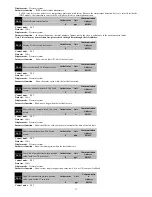
Case2
:
motor uses 17bit encoder, when input instruction is 5600 pulses, servo motor rotate one circle
:
17
16
15
1 131072
1
2
1
=
=
=
5600
5600
5600
1400
2
2
2
N
C
G
P
The parameters can be set
:
Setting way I
:
P1-26=17
,
P1-27=1
,
P1-28=5600
Setting way II
:
P1-26=16
,
P1-27=2
,
P1-28=5600
Setting way III
:
P1-26=15
,
P1-27=1
,
P1-28=1400
④
Electronic gear ratio for the recommended range
(
when uses 2500ppr encoder
)
1
1000
1000
G
⑤
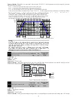
When it need switching frequently among the different electronic gear ratio, it can modify P1-27
、
P1-28 by communication mode
online; also can by setting two DI terminals for 20 (GNUM0) and 21 (GNUM1) function, then to switch through external DI input. at this
time, the corresponding electronic gear numerator as shown below
:
GNUM0
GNUM1
Effective electronic gear
numerator
0
0
P1-27
0
1
P1-29
1
0
P1-30
1
1
P1-31


