Bringing the Benefits of Real-Time Data Collection to the World
Sutron Corporation, Tel: 703-406-2800,
http://www.sutron.com
40
each output. This is especially important for sensors that take a significant time to measure
(imagine taking 5 separate measurements to obtain 5 parameters from an SDI sensor that takes
30 seconds to measure!). In addition, for some sensors, it may be important to ensure parameters
were measured at the same time.
To ensure only one measurement is made for all outputs of a single sensor,
the I/O device
configuration for each sensor entry representing a separate output, must be the same
. The
I/O device configuration consists of different parameters for different types of sensors. If the
sensor reads an analog input, then the analog input’s module and channel must be the same. If
the sensor reads a com port to obtain its input, then the com port must be the same. For SDI-12
sensor’s, the SDI-12 address and command must be the same. Note: the I/O device configuration
must be set the same
when creating the sensor entry
. Changing the configuration to be the
same after the entry has been made, does not result in “linking” any outputs.
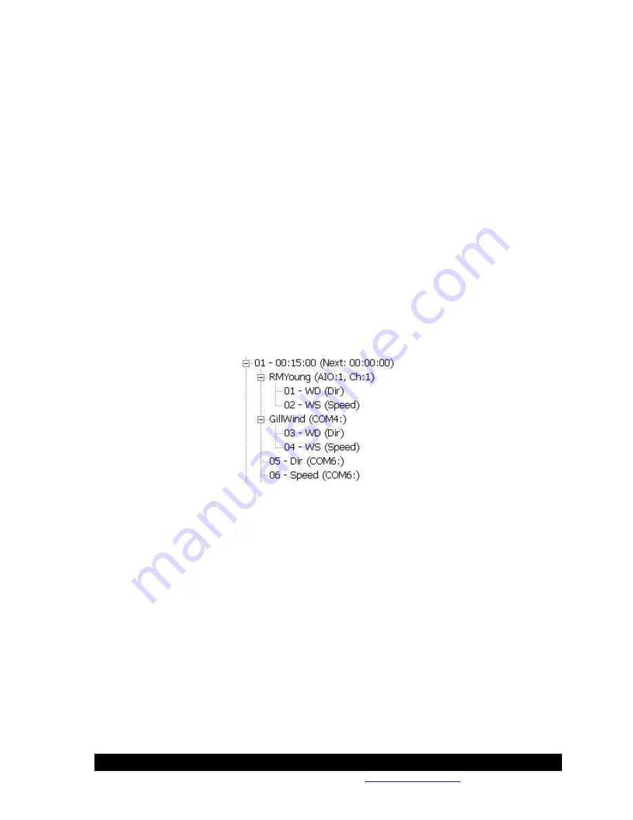
In the example below, the Dir and Speed outputs of the RMYoung sensor are linked. One
measurement of the sensor will be made every 15 minutes to obtain both values, Dir and Speed.
The same is the case for the GillWind sensor on COM4. However, the GillWind sensor on
COM5 does not have its outputs linked. This would happen if, for example, the Speed sensor
entry was created with the selection of COM7 and then changed to COM6 to match the Dir
entry.
Once outputs are linked,
a change to one will affect all linked outputs
. Using the above as an
example, if you select the GillWind Dir entry and change its com port to COM3, it will change
for the Speed setting as well.
Once an output has been linked, you must delete the entry to “unlink” it. Hence, to fix the fact
that the Speed output of the GillWind sensor on COM6 is not linked to the Dir output, you would
first delete the Speed entry, and then re-add it, making sure to set the com port setting to COM6
in the process.
Event Driven Sensors
The vast majority of sensors measure when told to, i.e., according to the measurement schedule
you define. The exception to this rule occurs when using a sensor with an
Event
option checked
(like BinIn). Every time an
Event
occurs, the entire set of sensors defined under the measurement
schedule will be measured. For example, if you had an EZSetup measurement schedule with the
BinIn block (
Event checked)
and an sdi-12 sensor, every time the BinIn detected a change of
state, the SDI-12 sensor would also be measured.
Summary of Contents for Xpert2
Page 2: ......
Page 11: ...Chapter 1 Introduction...
Page 16: ......
Page 17: ...Chapter 2 Getting Started...
Page 86: ......
Page 87: ...Chapter 4 Graphical Setup Diagrams...
Page 104: ......
Page 105: ...CHAPTER 5 EXAMPLE SETUPS...
Page 128: ......
Page 129: ......
Page 130: ......
Page 131: ...Chapter 7 Installation...
Page 140: ......
Page 141: ...Chapter 8 Maintenance and Troubleshooting...
Page 145: ...Appendix A Setup Blocks...
Page 266: ......
Page 267: ...Appendix B Updating the Firmware...
Page 290: ......
Page 291: ...Appendix E Software Development Kit SDK...
Page 293: ...Appendix F Creating Custom Voice Files...
Page 330: ......


