WAGO-I/O-SYSTEM 750
Appendix 111
750-657 IO-Link Master
Manual
Version 1.0.2, valid from FW/HW-Version 02/01
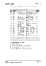
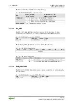
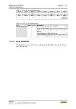
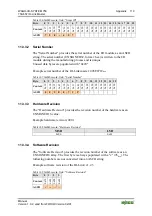
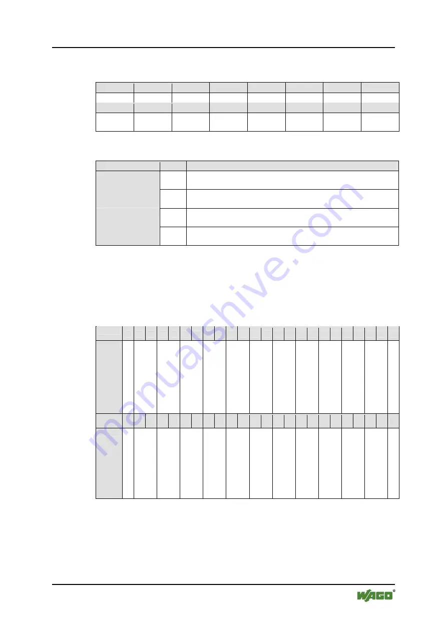
The table below provides an overview of the individual bits.
Table 87: IOLM_FEATURE, Data structure
Bit 15
Bit 14
Bit 13
Bit 12
Bit 11
Bit 10
Bit 9
Bit 8
0 0 0 0 0 0 0 0
Bit 7
Bit 6
Bit 5
Bit 4
Bit 3
Bit 2
Bit 1
Bit 0
0 0 0 0 0 0
KBUS_
DIAG_EN
IOLM_
DIAG_EN
Table 88: IOLM_FEATURE, Structure description
Bit
Value Description
0
No diagnostic telegrams are transferred to the control via the
Mailbox.
IOLM_DIAG_EN
1
Diagnoses of the I/O module are transferred to the control via the
Mailbox.
0
No fault condition is transferred via the status byte of the internal
bus.
KBUS_DIAG_EN
1
The fault status of the I/O module and attached IO-Link devices is
transferred cyclically via the status byte of the internal bus.
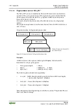
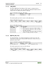
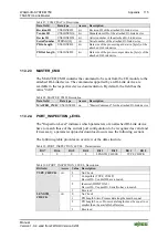
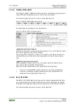
11.3.1.6 IOLM_PAB_STRUCT
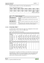
The IOLM_PAB_STRUCT data field contains the configuration for the internal
bus process image. Access occurs via an IOL-CALL.
Table 89: IOLM_PAB_STRUCT, Data structure
Byte
0
1
2
3
4
5
6
7
8
9 10 11 12 13 14 15 16 17 18 19 20 21 22 23
Content
S
E
GM
EN
T_
MO
D
E
SIO_OFF
S
ET
SI
O_
LENG
TH
PORT
1_OUT_
SEGM_OFFS
ET
POR
T
1_
O
U
T
_
SEGM_
L
EN
GTH
PORT
2_ OUT
_
SEGM_OFFS
ET
PORT
2_ OUT
_
SEGM_
L
EN
GTH
PORT
3_ OUT
_
SEGM_OFFS
ET
PORT
3_ OUT
_
SEGM_
L
EN
GTH
PORT
4_ OUT
_
SEGM_OFFS
ET
PORT
4_ OUT
_
SEGM_
L
EN
GTH
POR
T
1_
IN
_
SEGM_OFFS
ET
PORT
1_ IN
Byte
24 25 26 27 28 29 30 31 32 33 34 35 36
-
-
-
-
-
-
-
-
-
-
-
Content
SEGM_
L
EN
GTH
POR
T
2_
I
N_
SEGM_OFFS
ET
POR
T
2_
I
N_
SEGM_
L
EN
GTH
POR
T
3_
I
N_
SEGM_OFFS
ET
POR
T
3_
I
N_
SEGM_
L
EN
GTH
POR
T
4_
I
N_
SEGM_OFFS
ET
POR
T
4_
I
N_
SEGM_
L
EN
GTH
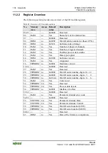
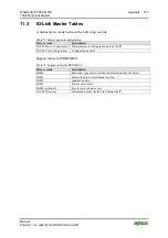
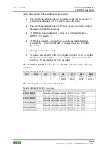
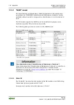
The parameters are specified in the "Bit" unit. The offset refers to the start of the
internal bus process image. For a segment length of 0, no process data from the
attached IO-Link device is written to the internal bus process image (IN) or
process by the internal bus process image (OUT).

