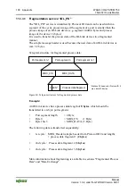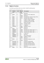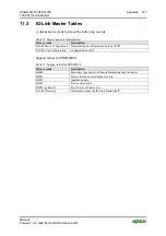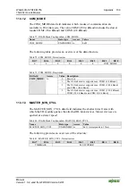
114 Appendix
WAGO-I/O-SYSTEM
750
750-657 IO-Link Master
Manual
Version 1.0.2, valid from FW/HW-Version 02/01
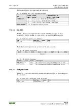
This value is active when the power supply is switched on next. The written value
can then be read back in the PORT_CONFIG port parameter.
Settings for the port cycle time are available in section 11.3.1.3.
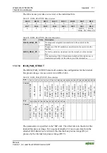
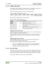
Table 94: PORT_CONFIG, Data structure
Bit 15
Bit 14
Bit 13
Bit 12
Bit 11
Bit 10
Bit 9
Bit 8
PORT_CYCLE_TIME
Bit 7
Bit 6
Bit 5
Bit 4
Bit 3
Bit 2
Bit 1
Bit 0
PORT_PHYSICS PORT_CYCLE_MODE
PORT_OPERATION_MODE
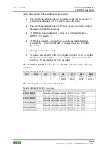
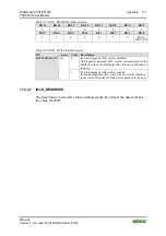
Table 95: SEGMENT_MODE, Description
Bit field
Access
Value Description
0
Port is inactive
1
Port is DI (digital input, default)
2
Port is DO (digital output)
r/w
3
Port mode SCAN (IO-Link)
4
Port mode COM1 (IO-Link)
5
Port mode COM2 (IO-Link
ro
6
Port mode COM3 (IO-Link)
PORT_OPERATION_MODE
- 7..15
Reserved
0 Free
(default)
1
Synchronous (not supported)
2 Fixed
value
PORT_CYCLE_MODE
ro
3 Reserved
0..2 Reserved
PORT_PHYSICS
ro
3
IO-Link PHY 2 (default)
PORT_CYCLE_TIME
r/w
Var.
This is the required value for the cycle time
on an IO-Link port. With a value of "0x00",
the minimum cycle type of the attached IO-
Link device is used if the master supports the
MIN_CYLCE_TIME of the device.
11.3.2.2 COMP_DATA
The COMP_DATA data field contains data from the IO-Link device connected to
the port. The data is used (partially) used when starting a device to check validity.
By default, all data bytes have the value 0x00.
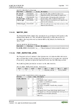
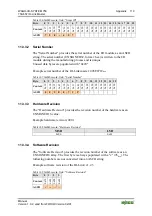
Table 96: IOLM_PAB_STRUCT, Data structure
Byte
0
1 2 3
4
5
6
7
8
9 10 11 12 13 14 15 16 17 18 19 20 21 22 23
Content
Rev
ision
ID
V
en
dor
ID
De
vice ID
Serial
Nu
mbe
r
PD
In
Le
ngt
h
PDOu
t Len
gt
h

