APPENDIX F REVISION HISTORY
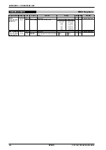
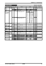
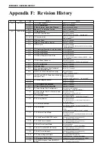
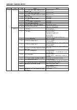
Appendix F: Revision History
Rev. No.
Date
Page
Section
Details
0.8
2007.9.21
1-3
1.3.1 Pinout Diagram
Figure 1.3.1.1 changed
1-4
1.3.2 Pin Descriptions
Table 1.3.2.1 changed
23-1
23 Basic External Connection Diagram
Figure changed and added
AP-31
Appendix D: Initialization Routine
Sample program changed
0.9
2007.10.28
1-2
1-2 Block Diagram
Figure 1.2.1 changed
2-1
2.1 S1C17 Core Features
Description changed
“It features low power consumption, … are widely used.”
2-3 to 2-5 2.3 Command Set
Table 2.3.1 changed
Note (*2) added
2-7
2.4 Vector Table
Table 2.4.1 changed
3-1
3 Memory Map and Bus Control
Figure 3.1 changed
3-2
3.1 Bus Cycle
Description changed
“Interrupt processing stack operation involves reading
… in the last 24 bits.”
3-2
3.1.2 Command Execution Cycle Restrictions
Section changed
3-3
3.2 Internal ROM Area
Section title changed
3-4
3.3 Internal RAM Area
Section title changed
3-5
3.4 Internal Peripheral Circuit Area
Description changed
“The 1 Kbyte area starting at address 0x4000 … and
control registers.”
5-3
5.2 Initial Reset Sequence
Description changed
“CPU startup waits for … OSC3 clock frequency”
6-1
6.1 ITC Configuration
Figure 6.1.1 changed
6-2
6.2 Vector Table
Table 6.2.1 changed
6-3
6.3.2 Interrupt Request from Peripheral
Module and Interrupt Flag
Table 6.3.2.1 changed
6-8
6.3.6 S1C17 Core Interrupt Processing
Description added
“- ITEN … has been set to 1.”
6-11
6.6 HALT and SLEEP Mode Cancellation by
Interrupt Factors
Section title changed
Description changed
“HALT and SLEEP modes are … in Appendix B.”
6-13
6.7 Control Register Details
Table 6.7.2 changed
6-15
Table 6.7.4 changed
7-1
7.1 OSC Module Configuration
Figure 7.1.1 changed
8-1
8.1 Clock Generator Configuration
Figure 8.1.1 changed
10-1
10.1 Input/Output Port Configuration
Description (note) changed
“Switch on the … using this function.”
10-2
10.2 Input/Output Port Pin Function Selec-
tion (Port MUX)
Description changed
“Resetting the … in Table 10.2.1).”
10-3
10.3 Data Input/Output
Description changed
“The input/output ports … P
x
IO[7:0] (P
x
_IO register).”
10-4
10.4 Pull-up Control
Description changed
“The input/output port contains a pull-up resistor, …
(P
x
_PU register).”
10-7
10.7 Port Input Interrupt
Description changed
“The interrupt controller … Interrupt Controller (ITC).”
10-24
10.9 Precautions
Description added
Pull-up
“- Input/output ports that are not used … enabled.”
11-3
11.2.2 External Clock Mode
Description changed
“For instructions on controlling chattering filter circuits,
… Function.”
11-8
11.6 16-bit Timer RUN/STOP Control
Description changed (one location only)
ITC
→
interrupt controller (ITC)
11-10
11.8 16-bit Timer Interrupts
Description changed (one location only)
ITC
→
interrupt controller (ITC)
12-2
12.2 8-bit Timer Count Mode
Description added
“Note: Make sure … count mode settings.”
12-6
12.6 8-bit Timer RUN/STOP Control
Description changed (one location only)
ITC
→
interrupt controller (ITC)
12-9
12.9 8-bit Timer Interrupts
Description changed (one location only)
ITC
→
interrupt controller (ITC)
12-15
12.10 Control Register Details
Description added (0x4206, D4)
“Note: Make sure … count mode settings.”
13-4
13.4 Compare Data Settings
Counter reset cycle calculation equation added
13-5
13.5 PWM & Capture Timer RUN/STOP
Control
Description changed (one location only)
ITC
→
interrupt controller (ITC)
Summary of Contents for S1C17001
Page 1: ...Technical Manual S1C17001 CMOS 16 BIT SINGLE CHIP MICROCONTROLLER ...
Page 33: ...4 POWER SUPPLY VOLTAGE 24 EPSON S1C17001 TECHNICAL MANUAL This page intentionally left blank ...
Page 63: ...6 INITERRUPT CONTROLLER 54 EPSON S1C17001 TECHNICAL MANUAL This page intentionally left blank ...
Page 87: ...8 CLOCK GENERATOR CLG 78 EPSON S1C17001 TECHNICAL MANUAL This page intentionally left blank ...
Page 91: ...9 PRESCALER PSC 82 EPSON S1C17001 TECHNICAL MANUAL This page intentionally left blank ...
Page 133: ...11 16 BIT TIMER T16 124 EPSON S1C17001 TECHNICAL MANUAL This page intentionally left blank ...
Page 211: ...16 STOPWATCH TIMER SWT 202 EPSON S1C17001 TECHNICAL MANUAL This page intentionally left blank ...
Page 219: ...17 WATCHDOG TIMER WDT 210 EPSON S1C17001 TECHNICAL MANUAL This page intentionally left blank ...
Page 241: ...18 UART 232 EPSON S1C17001 TECHNICAL MANUAL This page intentionally left blank ...
Page 277: ...20 I2 C 268 EPSON S1C17001 TECHNICAL MANUAL This page intentionally left blank ...
Page 313: ...25 PACKAGE 304 EPSON S1C17001 TECHNICAL MANUAL This page intentionally left blank ...


