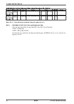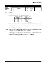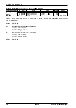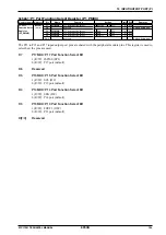
10 INPUT/OUTPUT PORT (P)
S1C17001 TECHNICAL MANUAL
EPSON
89
10.7 Port Input Interrupt
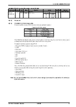
Ports P0 and P1 include input interrupt functions.
Select which of the 16 ports are to be used for interrupts based on requirements. You can also select whether inter-
rupts are generated for either the rising edge or falling edge of input signals.
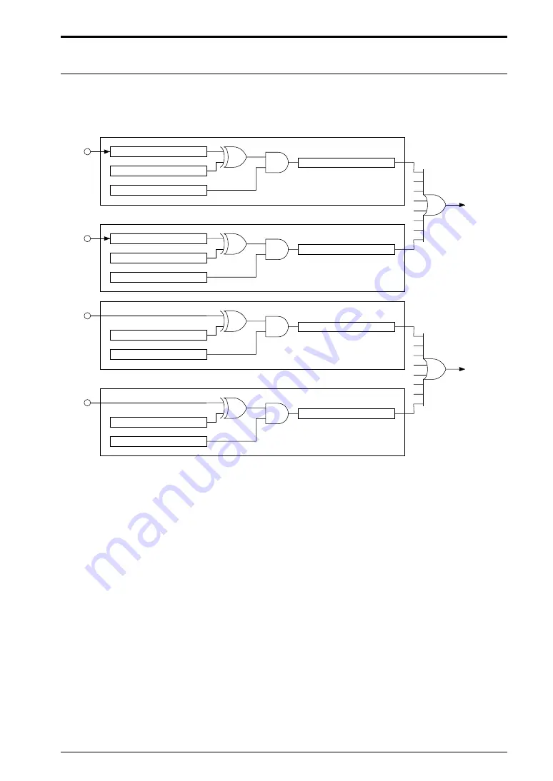
Figure 10.7.1 illustrates the port input interrupt circuit configuration.
Chattering filter
Interrupt flag
Interrupt enable
Interrupt edge selection
P00
P0CF1[2:0]
P0EDGE0
P0IF0
P0IE0
P07
P0CF2[2:0]
P0EDGE7
P0IF7
P0IE7
• • •
P10
P1EDGE0
P1IF0
P1IE0
P17
P1EDGE7
P1IF7
P1IE7
• • •
P0 port
interrupt
request
(to ITC)
P1 port
interrupt
request
(to ITC)
Figure 10.7.1: Port input interrupt circuit configuration
Interrupt port selection
Select the port generating an interrupt using P
x
IE[7:0] (P
x
_IMSK register).
∗
P0IE[7:0]
: P0[7:0] Port Interrupt Enable Bits in the P0 Port Interrupt Mask (P0_IMSK) Register (D[7:0]/0x5205)
∗
P1IE[7:0]
: P1[7:0] Port Interrupt Enable Bits in the P1 Port Interrupt Mask (P1_IMSK) Register (D[7:0]/0x5215)
Setting
P
x
IE[7:0] to 1 enables interrupt generation by the corresponding port. Setting to 0 (default) disables in-
terrupt generation.
The interrupt controller must also be set to actually generate an interrupt. For more information on making in-
terrupt controller settings, refer to “6. Interrupt Controller (ITC).”
Interrupt edge selection
Port input interrupts can be generated at either the rising edge or falling edge of the input signal. Select the edge
used to generate interrupts using P
x
EDGE[7:0] (P
x
_EDGE register).
∗
P0EDGE[7:0]
: P0[7:0] Port Interrupt Edge Select Bits in the P0 Port Interrupt Edge Select (P0_EDGE)
Register (D[7:0]/0x5206)
∗
P1EDGE[7:0]
: P1[7:0] Port Interrupt Edge Select Bits in the P1 Port Interrupt Edge Select (P1_EDGE)
Register (D[7:0]/0x5216)
Setting
P
x
EDGE[7:0] to 1 generates port input interrupts at the input signal falling edge. Setting it to 0 (default)
generates interrupts at the rising edge.
Summary of Contents for S1C17001
Page 1: ...Technical Manual S1C17001 CMOS 16 BIT SINGLE CHIP MICROCONTROLLER ...
Page 33: ...4 POWER SUPPLY VOLTAGE 24 EPSON S1C17001 TECHNICAL MANUAL This page intentionally left blank ...
Page 63: ...6 INITERRUPT CONTROLLER 54 EPSON S1C17001 TECHNICAL MANUAL This page intentionally left blank ...
Page 87: ...8 CLOCK GENERATOR CLG 78 EPSON S1C17001 TECHNICAL MANUAL This page intentionally left blank ...
Page 91: ...9 PRESCALER PSC 82 EPSON S1C17001 TECHNICAL MANUAL This page intentionally left blank ...
Page 133: ...11 16 BIT TIMER T16 124 EPSON S1C17001 TECHNICAL MANUAL This page intentionally left blank ...
Page 211: ...16 STOPWATCH TIMER SWT 202 EPSON S1C17001 TECHNICAL MANUAL This page intentionally left blank ...
Page 219: ...17 WATCHDOG TIMER WDT 210 EPSON S1C17001 TECHNICAL MANUAL This page intentionally left blank ...
Page 241: ...18 UART 232 EPSON S1C17001 TECHNICAL MANUAL This page intentionally left blank ...
Page 277: ...20 I2 C 268 EPSON S1C17001 TECHNICAL MANUAL This page intentionally left blank ...
Page 313: ...25 PACKAGE 304 EPSON S1C17001 TECHNICAL MANUAL This page intentionally left blank ...

