


TPMC533 User Manual Issue 1.0.1
Page 30 of 107
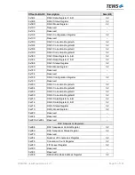
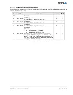
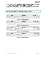
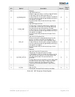
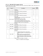
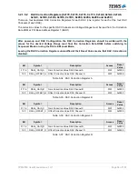
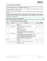
3.2.1.3.3
Number of Conversions Register (0x12C)
Bit
Symbol
Description
Access
Reset
Value
31:28
-
Reserved
-
-
27:0
ADC_SEQ_NUM_CONV
Number of Conversions to be performed
Set to '0' for continuous analog-to-digital conversions.
Normal Mode:
Number of conversions (after IU_CONV_START was set)
per requested block of analog-to-digital conversions.
When the configured Number of Conversions has been
performed, the conversion process is stopped (until software
sets the IU_CONV_START bit again) and the
IU_CONV_ACTIVE bit in the ADC Sequencer Status
Register is cleared.
Frame Mode:
Number of analog-to-digital conversions per Frame Trigger.
When the configured Number of Conversions (per frame)
has been performed, the conversion process is stopped
(until the next Frame Trigger event occurs) and the
IU_CONV_ACTIVE bit in the ADC Sequencer Status
Register is cleared.
R/W
0x000
0000
Table 3-23: Number of Conversions Register
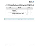
Note that every time the ADC Sequencer triggers a conversion, all eight ADC Channels of all ADCs
configured to operate in Sequencer Mode are updated simultaneously.
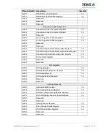
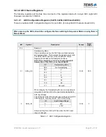
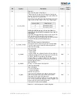
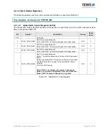
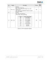
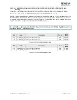
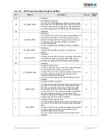
3.2.1.3.4
Conversion Count Register (0x130)
Bit
Symbol
Description
Access
Reset
Value
31:28
-
Reserved
-
-
27:0
ADC_SEQ_CONV_COUNT
Number of Conversions that have been performed
Normal Mode:
The value is automatically reset when the (next) Input Unit
Start Conversion is initiated in the ADC Sequencer
Control Register.
Frame Mode:
The value is automatically reset at a Frame Trigger event
(except for the case when an Input Unit Frame Error
occurred).
R
0x000
0000
Table 3-24: Conversion Count Register


