2003 Microchip Technology Inc.
DS39582B-page 221
PIC16F87XA
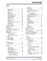
INDEX
A
A/D
................................................................................... 127
Acquisition Requirements
........................................ 130
ADCON0 Register
.................................................... 127
ADCON1 Register
.................................................... 127
ADIF Bit
.................................................................... 129
ADRESH Register
.................................................... 127
ADRESL Register
.................................................... 127
Analog Port Pins
.................................................. 49
,
51
Associated Registers and Bits
................................. 133
Calculating Acquisition Time
.................................... 130
Configuring Analog Port Pins
................................... 131
Configuring the Interrupt
.......................................... 129
Configuring the Module
............................................ 129
Conversion Clock
..................................................... 131
Conversions
............................................................. 132
Converter Characteristics
........................................ 194
Effects of a Reset
..................................................... 133
GO/DONE Bit
........................................................... 129
Internal Sampling Switch (Rss) Impedance
............. 130
Operation During Sleep
........................................... 133
Result Registers
....................................................... 132
Source Impedance
................................................... 130
A/D Conversion Requirements
......................................... 195
Absolute Maximum Ratings
............................................. 173
ACKSTAT
......................................................................... 101
ADCON0 Register
.............................................................. 19
ADCON1 Register
.............................................................. 20
Addressable Universal Synchronous Asynchronous
Receiver Transmitter. See USART.
ADRESH Register
.............................................................. 19
ADRESL Register
.............................................................. 20
Analog-to-Digital Converter. See A/D.
Application Notes
AN552 (Implementing Wake-up
on Key Stroke)
................................................... 44
AN556 (Implementing a Table Read)
........................ 30
Assembler
MPASM Assembler
.................................................. 167
Asynchronous Reception
Associated Registers
....................................... 118
,
120
Asynchronous Transmission
Associated Registers
............................................... 116
B
Banking, Data Memory
................................................. 16
,
22
Baud Rate Generator
......................................................... 97
Associated Registers
............................................... 113
BCLIF
................................................................................. 28
BF
..................................................................................... 101
Block Diagrams
A/D
........................................................................... 129
Analog Input Model
.......................................... 130
,
139
Baud Rate Generator
................................................. 97
Capture Mode Operation
........................................... 65
Comparator I/O Operating Modes
............................ 136
Comparator Output
.................................................. 138
Comparator Voltage Reference
............................... 142
Compare Mode Operation
......................................... 66
Crystal/Ceramic Resonator Operation
(HS, XT or LP Osc Configuration)
.................... 145
External Clock Input Operation
(HS, XT or LP Osc Configuration)
.................... 145
Interrupt Logic
.......................................................... 153
MSSP (I
2
C Mode)
...................................................... 80
MSSP (SPI Mode)
..................................................... 71
On-Chip Reset Circuit
.............................................. 147
PIC16F873A/PIC16F876A Architecture
...................... 6
PIC16F874A/PIC16F877A Architecture
...................... 7
PORTC
Peripheral Output Override
(RC2:0, RC7:5) Pins
.................................. 46
Peripheral Output Override (RC4:3) Pins
.......... 46
PORTD (in I/O Port Mode)
......................................... 48
PORTD and PORTE (Parallel Slave Port)
................. 51
PORTE (In I/O Port Mode)
......................................... 49
RA3:RA0 Pins
............................................................ 41
RA4/T0CKI Pin
.......................................................... 42
RA5 Pin
..................................................................... 42
RB3:RB0 Pins
............................................................ 44
RB7:RB4 Pins
............................................................ 44
RC Oscillator Mode
.................................................. 146
Recommended MCLR Circuit
.................................. 148
Simplified PWM Mode
............................................... 67
Timer0/WDT Prescaler
.............................................. 53
Timer1
....................................................................... 58
Timer2
....................................................................... 61
USART Receive
................................................117
,
119
USART Transmit
...................................................... 115
Watchdog Timer
...................................................... 155
BOR. See Brown-out Reset.
BRG. See Baud Rate Generator.
BRGH Bit
......................................................................... 113
Brown-out Reset (BOR)
.................... 143
,
147
,
148
,
149
,
150
BOR Status (BOR Bit)
............................................... 29
Bus Collision During a Repeated Start Condition
............ 108
Bus Collision During a Start Condition
............................. 106
Bus Collision During a Stop Condition
............................. 109
Bus Collision Interrupt Flag bit, BCLIF
............................... 28
C
C Compilers
MPLAB C17
............................................................. 168
MPLAB C18
............................................................. 168
MPLAB C30
............................................................. 168
Capture/Compare/PWM (CCP)
......................................... 63
Associated Registers
Capture, Compare and Timer1
.......................... 68
PWM and Timer2
............................................... 69
Capture Mode
............................................................ 65
CCP1IF
.............................................................. 65
Prescaler
........................................................... 65
CCP Timer Resources
............................................... 63
Compare
Special Event Trigger Output of CCP1
.............. 66
Special Event Trigger Output of CCP2
.............. 66
Compare Mode
.......................................................... 66
Software Interrupt Mode
.................................... 66
Special Event Trigger
........................................ 66
Interaction of Two CCP Modules (table)
.................... 63
PWM Mode
................................................................ 67
Duty Cycle
......................................................... 67
Example Frequencies/Resolutions (table)
......... 68
PWM Period
...................................................... 67
Special Event Trigger and A/D Conversions
............. 66
http://www.xinpian.net
提供单片机解密、IC解密、芯片解密业务
010-62245566 13810019655

