56
SLVSDC2B – FEBRUARY 2016 – REVISED AUGUST 2016
Product Folder Links:
Copyright © 2016, Texas Instruments Incorporated
9.3.9 Power Reset Congrol Module (PRCM)
The PRCM implements all clock management, reset control, and sleep-mode control.
9.3.10 Interrupt Monitor
The Interrupt Control module handles all interrupt from the external GPIO as well as interrupts from internal
analog circuits.
9.3.11 ADC Sense
The ADC Sense module is a digital interface to the SAR ADC. The ADC converts various voltages and currents
from the analog circuits. The ADC converts up to 11 channels from analog levels to digital signals. The ADC can
be programmed to convert a single sampled value.
9.3.12 I
2
C Slave
One I
2
C interface provides interface to the digital core from the system. This interface is an I
2
C slave and
supports low-speed and full-speed signaling. See the
section for more information.
9.3.13 SPI Master
The SPI master provides a serial interface to an external flash memory. The recommended memory is the
W25Q80DV 8-Mbit serial-flash memory. A memory of at least 2 Mbit is required. See the
section for more information.
9.3.14 Single-Wire Debugger Interface
The SWD interface provides a mechanism to directly master the digital core.
9.3.15 DisplayPort HPD Timers
To enable DisplayPort HPD signaling through PD messaging, two GPIO pins (GPIO4, GPIO5) are used as the
HPD input and output. When events occur on this pins during a DisplayPort connection through the Type-C
connector (configured in firmware), hardware timers trigger and interrupt the digital core to indicated needed PD
messaging.
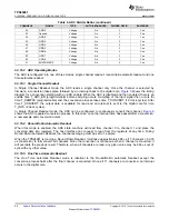
shows each I/O function when GPIO4/5 are configured in HPD mode. When HPD is not
enabled via firmware, both GPIO4 and GPIO5 remain generic GPIO and may be programmed for other functions.
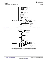
and
.
Table 5. HPD GPIO Configuration
HPD (Binary) Configuration
GPIO4
GPIO5
00
HPD TX
Generic GPIO
01
HPD RX
Generic GPIO
10
HPD TX
HPD RX
11
HPD TX/RX (bidirectional)
Generic GPIO

