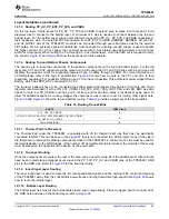
Memory Invalid
Enable VOUT_3V3
Release RESETZ
Check VBUS
Present
Rp/Rp
Check for
Rd/Rd
Present SWD
Monitor VBUS
VBUS Good
Rd/Rd Attached
VBUS Invalid
Rd/Rd Not
Attached
70
SLVSDC2B – FEBRUARY 2016 – REVISED AUGUST 2016
Product Folder Links:
Copyright © 2016, Texas Instruments Incorporated
Device Functional Modes (continued)
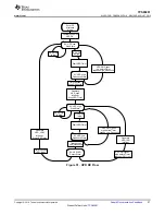
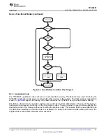
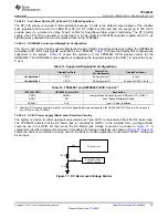
Figure 66. Memory Invalid Flow
9.5 Programming
9.5.1 SPI Master Interface
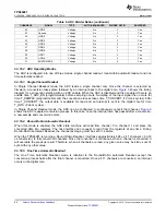
The TPS65981 loads flash memory during the
sequence. The SPI master electrical characteristics
are defined in
and timing characteristics are defined in
. The TPS65981 is
designed to power the flash from LDO_3V3 to support dead-battery or no-battery conditions, and therefore pull-
up resistors used for the flash memory must be tied to LDO_3V3. The flash memory IC must support 12 MHz
SPI clock frequency. The size of the flash must be at least 1 Mbyte (equivalent to 8 Mbit) to hold the standard
application code outlined in
. The SPI master of the TPS65981 supports SPI Mode 0. For Mode
0, data delay is defined such that data is output on the same cycle as chip select (SPI_SSZ pin) becomes active.
The chip select polarity is active-low. The clock phase is defined such that data (on the SPI_MISO and
SPI_MOSI pins) is shifted out on the falling edge of the clock (SPI_CLK pin) and data is sampled on the rising
edge of the clock. The clock polarity for chip select is defined such that when data is not being transferred the
SPI_CLK pin is held (or idling) low. The minimum erasable sector size of the flash must be 4 kB. The W25Q80
flash memory IC is recommended. Refer to TPS65981 I
2
C Host Interface Specification for instructions for
interacting with the attached flash memory over SPI using the host interface of the TPS65981.
9.5.2 I
2
C Slave Interface
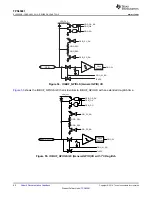
The TPS65981 has one I
2
C interface port. The I
2
C Port is comprised of the I2C_SDA, I2C_SCL, and I2C_IRQZ
pins. This interface provide general status information about the TPS65981, as well as the ability to control the
TPS65981 behavior, as well as providing information about connections detected at the USB-C receptacle and
supporting communications to and from a connected device and/or cable supporting BMC USB-PD.
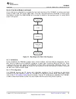
The port is an I
2
C slave. An interrupt mask is set for the I
2
C port that determines what events are interrupted on
the port. The interrupt mask is configurable in application code.


