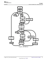
Enter DP
Alternate
Mode
S0: HPD Low
Wait State
Firmware enables
HPD RX
Start HPD Timer
HPD GPIO
is High
S1: HPD High
Debounce State
HPD GPIO
is low
HPD GPIO goes
low before Timer
reaches High_Debounce
Generate
HPD_High
interrupt,
Stop HPD Timer
Timer passes
High_Debounce
S2: HPD High
Wait State
HPD GPIO
is high
Start HPD Timer
HPD GPIO
is low
S3: HPD Low
Debounce State
HPD GPIO goes
high before Timer
reaches Low_Debounce
S4: HPD IRQ
Detect State
Timer passes
Low_Debounce
Generate
HPD_IRQ
Interrupt
HPD GPIO goes
high before Timer
reaches IRQ_Limit
Generate
HPD_LOW
Interrupt,
Stop HPD Timer
Timer Passes
IRQ_Limit
58
SLVSDC2B – FEBRUARY 2016 – REVISED AUGUST 2016
Product Folder Links:
Copyright © 2016, Texas Instruments Incorporated
Figure 52. HPD TX Flow Diagram
9.3.16 ADC
The TPS65981 ADC is shown in
. The ADC is a 10-bit successive approximation ADC. The input to the
ADC is an analog input multiplexer that supports multiple inputs from various voltages and currents in the device.
The output from the ADC is available to be read and used by application firmware. Each supply voltage into the
TPS65981 is available to be converted including the port power path inputs and outputs. All GPIO, the C_CCn
pins, the charger detection voltages are also available for conversion. To read the port power path current
sourced to VBUS, the high-voltage and low-voltage power paths are sensed and converted to voltages to be
read by the ADC. For the external FET path, the difference in the SENSEP and SENSEN voltages is converted
to detect the current (I_PP_EXT) that is sourced through this path.

