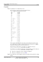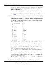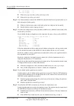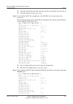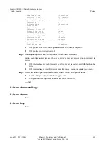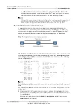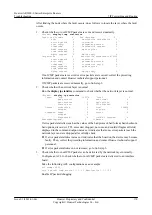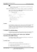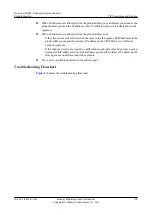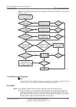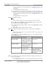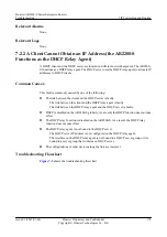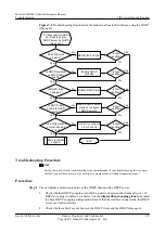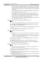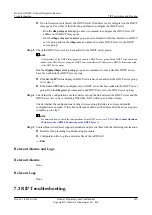
According to the numbers of sent and received ICMP packets, you can locate the direction
in which the fault occurs:
–
If the following conditions are all met, it indicates that the source end sends Request
packets but does not receive any Response packet, and the destination end does not receive
the Request packets.
–
On the source end, the value of the Output:echo field increases normally but the value
of the Input:echo field does not increase.
–
On the destination end, the numbers of sent and received packets remain unchanged.
In this case, you can determine that the fault occurs in the direction from the source end
to the destination end.
–
If the following conditions are all met, it indicates that the source end sends Request
packets but does not receive any Response packet, and the destination end receives the
Request packets and sends Response packets.
–
On the source end, the value of the Output:echo field increases normally but the value
of the Input:echo field does not increase.
–
On the destination end, the numbers of sent and received packets increase normally.
In this case, you can determine that the fault occurs in the direction from the destination
end to the source end.
After determining the direction in which the fault occurs, go to Step 4.
l
If the number of ICMP packets still increases, it indicates that the board or the device receives
other ICMP packets. Do as follows to locate the fault.
NOTE
Before performing subsequent operations, ensure that:
l
Services on the current network will not be affected.
l
No traffic policies are applied to interfaces.
1.
Configure an ACL on each device to match Ping packets by using source and destination
addresses.
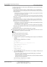
Take the following configurations as an example:
statistics enable
#
acl number 3000
rule 5 permit ip source 1.1.1.1 0 destination 1.1.1.2 0
#
traffic classifier 3000 operator or
if-match acl 3000
#
traffic behavior 3000
#
traffic policy 3000
statistics enable
classifier 3000 behavior 3000
2.
Run the
traffic-policy
command in the interface view to configure a traffic policy and
apply the ACL to interfaces.
–
On the source end and destination end, apply the traffic policy in the inbound
direction of interfaces on both ends.
–
On the intermediate device, apply the traffic policy in both the inbound and outbound
directions of the associated interface.
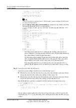
Take the following configurations as an example:
#
interface GigabitEthernet1/0/0
Huawei AR2200-S Series Enterprise Routers
Troubleshooting
7 IP Forwarding and Routing
Issue 01 (2012-01-06)
Huawei Proprietary and Confidential
Copyright © Huawei Technologies Co., Ltd.
167

