Notes
PES12N3 User Manual
10 - 1
June 7, 2006
Chapter 10
Test and Debug
Device Test Modes
In addition to normal operating mode, the PES12N3 has four test modes. These test modes are selected
by asserting the appropriate test mode value on the Switch Mode (SWMODE[3:0]) pins during a funda-
mental reset.
Switch modes are summarized in Chapter 2, Table 2.2. When one of the switch test modes described
below is selected, the normal fundamental reset sequence, described in section Fundamental Reset on
page 2-5, is bypassed and the following reset sequence is executed.
1. Wait for the fundamental reset condition to clear (e.g., negation of PERSTN).
2. The SerDes is initialized.
3. Sample the boot configuration signals listed in Table 2.2.
4. The SWMODE[3:0] signals are examined to determine the switch operating mode.
5. The slave SMBus is taken out of reset and initialized.
6. Device test mode operation begins.
While the device is in test mode, the slave SMBus is operational and may be used to read and write any
register in the device.
The Invert Bit-Stream (IBS) bit in the port A Test Mode Control (PA_TMCTL) allows the transmitted bit
stream of any of the 24 lanes to be inverted. This capability may be used to validate the correct operation of
the following test modes (i.e., validate that a test mode does in fact correctly check and report errors).
All test modes that externally loop back data transmitted by the PES12N3 to a PES12N3 input SerDes
may be configured to perform this loopback on-chip by setting the appropriate bit(s) in the ILBE field and
configuring the LBDRVOP bit, both of which are in a port’s SERDESCFG register.
10-bit Loopback Test Mode (SWMODE[3:0] = 0x8)
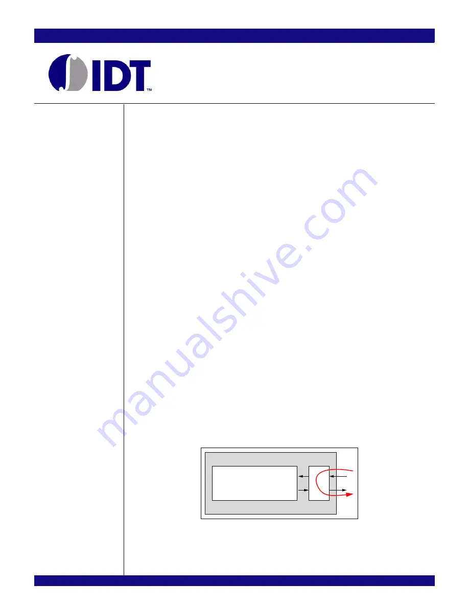
In 10-bit loopback test mode, data received on a SerDes lane is looped back to its output. This loopback
occurs in the SerDes and is graphically illustrated in Figure 10.1. After reset, all 24-lanes of the device enter
this test mode. However, individual ports may be enabled and disabled. A port is enabled when all of the
bits in the PAEN, PBEN or PCEN field corresponding to the port are set in the Port A Test Mode Control
(PA_TMCTL) register. If any bit in one of these fields is cleared, then the corresponding port is disabled.
The incoming serial bit stream must be synchronous to the PES12N3 reference clock. This test mode
has no failure or synchronization conditions.
Figure 10.1 10-bit Loopback Test Mode
Ser
D
es
PES12N3
10b
Other
Logic
Summary of Contents for 89HPES12N3
Page 10: ...IDT Table of Contents PES12N3 User Manual iv June 7 2006 Notes...
Page 14: ...IDT List of Figures PES12N3 User Manual viii June 7 2006 Notes...
Page 36: ...IDT Clocking Reset and Initialization Reset PES12N3 User Manual 2 8 June 7 2006 Notes...
Page 40: ...IDT Link Operation Slot Power Limit Support PES12N3 User Manual 3 4 June 7 2006 Notes...
Page 50: ...IDT Switch Operation Switch Core Errors PES12N3 User Manual 4 10 June 7 2006 Notes...
Page 54: ...IDT Power Management Active State Power Management PES12N3 User Manual 5 4 June 7 2006 Notes...
Page 62: ...IDT Hot Plug and Hot Swap Hot Swap PES12N3 User Manual 6 8 June 7 2006 Notes...
Page 78: ...IDT SMBus Interfaces Slave SMBus Interface PES12N3 User Manual 7 16 June 7 2006 Notes...
Page 148: ...IDT Test and Debug SerDes Test Clock PES12N3 User Manual 10 6 June 7 2006...
Page 158: ...IDT JTAG Boundary Scan Usage Considerations PES12N3 User Manual 11 10 June 7 2006 Notes...


