IDT About This Manual
Numeric Representations
PES12N3 User Manual
2
June 7, 2006
Notes
To define the active polarity of a signal, a suffix will be used. Signals ending with an ‘N’ should be inter-
preted as being active, or asserted, when at a logic zero (low) level. All other signals (including clocks,
buses and select lines) will be interpreted as being active, or asserted when at a logic one (high) level. To
define buses, the most significant bit (MSB) will be on the left and least significant bit (LSB) will be on the
right. No leading zeros will be included.
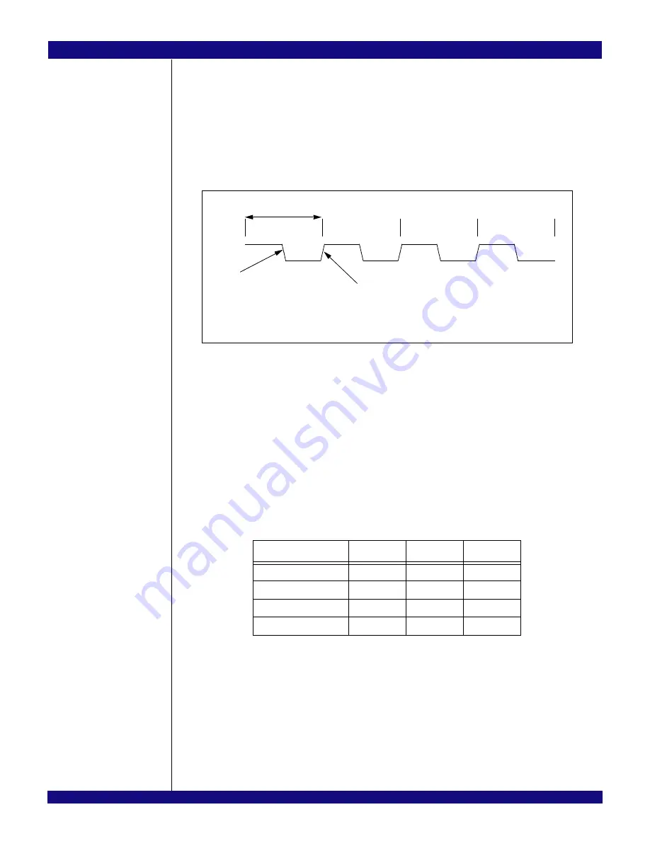
Throughout this manual, when describing signal transitions, the following terminology is used. Rising
edge indicates a low-to-high (0 to 1) transition. Falling edge indicates a high-to-low (1 to 0) transition. These
terms are illustrated in Figure 1.
Figure 1 Signal Transitions
Numeric Representations
To represent numerical values, either decimal, binary, or hexadecimal formats will be used. The binary
format is as follows: 0bDDD, where “D” represents either 0 or 1; the hexadecimal format is as follows:
0xDD, where “D” represents the hexadecimal digit(s); otherwise, it is decimal.
The compressed notation ABC[x|y|z]D refers to ABCxD, ABCyD, and ABCzD.
The compressed notation ABC[x..y]D refers to ABCxD, ABC(x+1)D, ABC(x+2)D,... ABCyD.
Data Units
The following data unit terminology is used in this document.
In quadwords, bit 63 is always the most significant bit and bit 0 is the least significant bit. In double-
words, bit 31 is always the most significant bit and bit 0 is the least significant bit. In words, bit 15 is always
the most significant bit and bit 0 is the least significant bit. In bytes, bit 7 is always the most significant bit
and bit 0 is the least significant bit.
The ordering of bytes within words is referred to as either “big endian” or “little endian.” Big endian
systems label byte zero as the most significant (leftmost) byte of a word. Little endian systems label byte
zero as the least significant (rightmost) byte of a word. See Figure 2.
Term
Words
Bytes
Bits
Byte
1/2
1
8
Word
1
2
16
Doubleword (Dword)
2
4
32
Quadword (Qword)
4
8
64
Table 1 Data Unit Terminology
1
2
3
4
high-to-low
transition
low-to-high
transition
single clock cycle
Summary of Contents for 89HPES12N3
Page 10: ...IDT Table of Contents PES12N3 User Manual iv June 7 2006 Notes...
Page 14: ...IDT List of Figures PES12N3 User Manual viii June 7 2006 Notes...
Page 36: ...IDT Clocking Reset and Initialization Reset PES12N3 User Manual 2 8 June 7 2006 Notes...
Page 40: ...IDT Link Operation Slot Power Limit Support PES12N3 User Manual 3 4 June 7 2006 Notes...
Page 50: ...IDT Switch Operation Switch Core Errors PES12N3 User Manual 4 10 June 7 2006 Notes...
Page 54: ...IDT Power Management Active State Power Management PES12N3 User Manual 5 4 June 7 2006 Notes...
Page 62: ...IDT Hot Plug and Hot Swap Hot Swap PES12N3 User Manual 6 8 June 7 2006 Notes...
Page 78: ...IDT SMBus Interfaces Slave SMBus Interface PES12N3 User Manual 7 16 June 7 2006 Notes...
Page 148: ...IDT Test and Debug SerDes Test Clock PES12N3 User Manual 10 6 June 7 2006...
Page 158: ...IDT JTAG Boundary Scan Usage Considerations PES12N3 User Manual 11 10 June 7 2006 Notes...


