


Chapter 6 Instruction Details
XBC E-Type Main Unit
6-71
Ver. 1
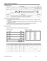
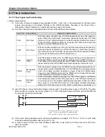
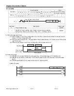
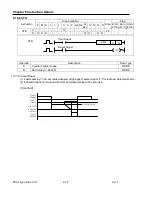
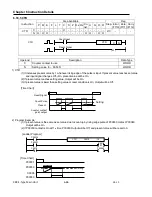
6.17.4 TMR
Instruction
Area Available
Step
Flag
P M K F L T C S Z D.x R.x
Co
nst.
U N D R
Error
(F110)
Zero
(F111)
Carry
(F112)
TMR
T
-
-
-
-
- O -
-
-
-
-
-
-
-
-
-
2/3
-
-
-
t
O O O -
-
-
-
-
-
-
- O O - O O
Operand
Description
Data Type
T
Timer Contact to use
WORD
t
Stands for timer’s setting value. Integer or word device available
Setting Time = Basic cycle (100ms, 10ms, 1ms) x Setting value( t)
WORD
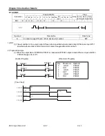
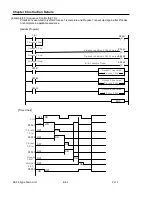
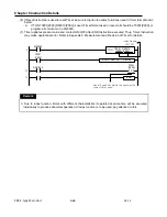
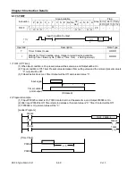
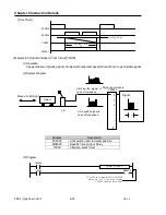
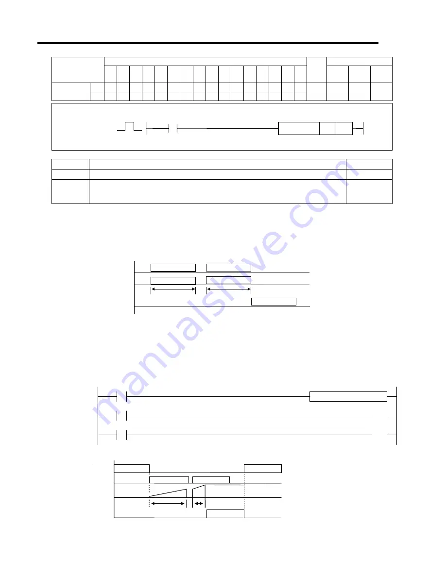
1) TMR (Accumulating Timer)
(1) If present value increases while input condition is allowed and its accumulated value reaches timer’s setting
value, Timer Contact will be ON. Accumulating timer keeps timer value even if power cut off when used in
non-volitile area.
(2) If Reset input condition is allowed, Timer Contact will be Off and present value “0”.
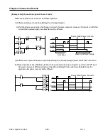
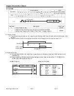
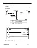
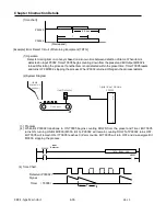
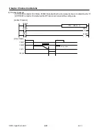
2) Program Example
(1) Where contact P0020 is repeatedly On, Off, and On then to make T0096 On and Output contact P0061 On
(t1 + t2 = 30sec).
(2) If Reset Signal P0023 is On, present value will be “0” and P0061 Off.
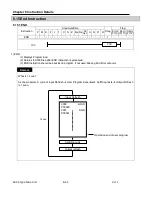
[Ladder Program]
TMR T0096 30
P00020
T0096
( )
P00061
P00023
( )
T0096
R
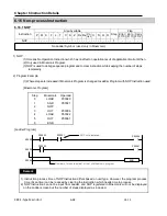
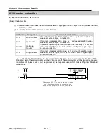
[Time Chart]
TMR
Input Condition Contact
TMR
T
t
Setting
(Present)
t = 20
t = 10
P00023
P00020
P00061
T0096
t1
t2
Setting time (t) = t1 + t2
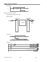
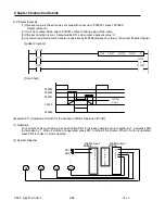
(Increased)
Input Signal
Present
accumulated
Timer contact
point output
Summary of Contents for XBC-DN10E
Page 1: ......
Page 10: ...Table of Contents Table of Contents 6 10 10 CLEAR ALL PLC 29...


