


S
ETUP
.E
XE
C-10
C
o
n
fi
g
u
re
M
en
u
T
u
n
in
g
P
a
ra
m
et
er
s
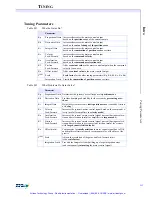
(step) error is possible. The range of values for integral gain is 0 to 32,767.
Derivative Gain
Use the derivative gain term like a damping factor. The derivative gain affects the analog com-
mand voltage or pulse rate based on the amount of position error change occurring in the last
two samples. The range of values for the derivative gain is 0 to 32,767.
Acceleration Feed-Forward
Use the acceleration feed-forward term to add extra output during acceleration to reduce fol-
lowing error. The range of values for the acceleration feed-forward is 0 to 32,767.
Velocity Feed-Forward
Use the velocity feed-forward term to add extra output during constant velocity to reduce fol-
lowing error. The range of values for the velocity feed-forward is 0 to 32,767.
I Maximum
Use the
I Maximum
limit to prevent “windup.” Generally, “windup” occurs in systems where
(very) high friction cannot be overcome without entering an oscillation mode. The
I Maximum
parameter sets the maximum voltage output by the integration term of the PID algorithm. The
range of values for the integration limit is 0 to 32,767.
Offset
Use the
Offset
parameter to compensate for other system offsets. The
Offset
parameter sets the
DAC output level. However, in most cases, the offset parameter should be set at 0.
Note that each axis also has an
internal offset
, which is in series with the
digital filter offset
(
Offset
parameter, which is visible on the SETUP program tuning screen). You use the
Offset
parameter to zero the DAC and Voltage-to-Frequency converter outputs, to prevent motion
when the axis is placed in idle mode.
The internal offset is set by the CONFIG.EXE program. After the CONFIG program has run,
the normal DAC offset should be under 3 millivolts (which will not produce step pulses). Tem-
perature drift is approximately 1 millivolt per degree C.
Only positive values of
Offset
will output steps, since the Voltage-to-Frequency converter can
only react to positive voltages. The range of values for the
Offset
is +/- 32,767.
Output Limit
Use the
Output Limit
parameter to limit the controller output (analog voltage or pulse rate) dur-
ing system tuning. For servo motors, this term limits the analog output voltage. For step mo-
tors, this term limits the step pulse output rate. The range for the output limit is 0 to 32,767.
This range corresponds to -10V to +10V for servos (i.e. 0.000305 volts/unit) or 0 to full scale
pulse rate for steps.
Shift Range
Use the
Shift Range
parameter to shift the range of the tuning parameters. The shift factor mul-
tiplies or divides all the filter parameters by a user specified power of two. For example, if the
shift factor = -3, then all the filter parameters will be divided by 8 (2
-3
= 1/8). If the shift factor
= 2, then all the parameters will be multiplied by 4. This is useful for unusual motors such as
air-bearing motors, voice-coil actuators and hydraulics or other actuators. The default param-
eter is -5, i.e. a multiplier of 2
-5
or 1/32.
Friction Feed-Forward
Use the friction feed-forward term to add extra output during any commanded velocity, to re-
duce
following error
caused by friction. The range of values for the friction feed-forward are
0 to 32,767.
Artisan Technology Group - Quality Instrumentation ... Guaranteed | (888) 88-SOURCE | www.artisantg.com


