O
PTO
C
ON
R
EFERENCE
F-10
C
ir
cu
it
E
x
a
m
p
le
s
C
o
n
n
ec
t
a
n
O
p
to
C
o
n
I
n
p
u
t
to
a
n
O
p
en
C
o
ll
ec
to
r
D
ri
ve
r
Connect an OptoCon Input to an Open Collector Driver
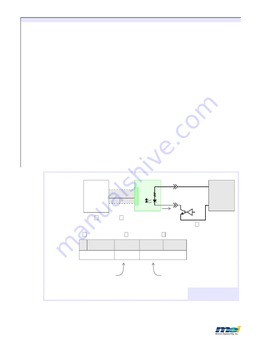
The next figure shows how to connect an OptoCon input to detect the state of an open col-
lector driver. This circuit will also work for
any
of the OptoCon inputs.
Use the MEI library functions
set_home_level(...)
or
set_boot_home_level(...)
to configure the
Home(0) input on the MEI motion controller for either
Active High
or
Active Low
event gen-
eration logic.
The truth table shows the values that the motion controller will read, depending upon the
state of the driver transistor and the configuration of the Home event logic. For example, if
the
In
= 1 (turning the transistor
On
), the Home input will be low (0), and if the Home event
logic is configured for
Active High
, the controller will
not
generate an event.
When
In
is high, the driver transistor is required to sink the current flowing through the opto-
isolator diode. The driver transistor must be capable of sinking this current. To calculate I
C
:
I
Sink
≅
(V – V
D
– V
CE
) / 2700
V
=
Your system’s power supply voltage
V
D
=
Voltage across diode, V
D
≅
1V
V
CE
=
Collector-emitter “
On”
voltage
for Q
For V = 24V,
V
CE
= 0.2V and I
C
≅
8.4 mA.
For V = 5V,
V
CE
= 0.2V and I
C
≅
1.4 mA.
2.7
LC/DSP
104/DSP
P2-2
+V
Common
CBL-100
Home(0
P2-31
P1
OptoCon
Open Collector Driver to
OptoCon Input
In
Q
I
Sink
Power
Supply
5 - 24V
Home Input
Active High
Active Low
In
Transistor “Q”
(State)
(Event?)
(Event?)
1
On
0
No
Yes
0
Off
1
Yes
No
Use
home_switch(...)
to read the Home input state.
Use
axis_state(...)
to read
the event generation.
3
2
1
1
2
3
For input circuitry,
see schematics on
page F-8.
V
D
Artisan Technology Group - Quality Instrumentation ... Guaranteed | (888) 88-SOURCE | www.artisantg.com

