background image

 2003 Microchip Technology Inc.

DS39582B

PIC16F87XA

Data Sheet

28/40/44-Pin Enhanced Flash

Microcontrollers

http://www.xinpian.net

提供单片机解密、IC解密、芯片解密业务

010-62245566    13810019655

Summary of Contents for PIC16F87XA

Page 1: ...2003 Microchip Technology Inc DS39582B PIC16F87XA Data Sheet 28 40 44 Pin Enhanced Flash Microcontrollers http www xinpian net IC 010 62245566 13810019655...

Page 2: ...orporated Printed in the U S A All Rights Reserved Printed on recycled paper Note the following details of the code protection feature on Microchip devices Microchip products meet the specification co...

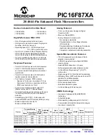
Page 3: ...erter A D Brown out Reset BOR Analog Comparator module with Two analog comparators Programmable on chip voltage reference VREF module Programmable input multiplexing from device inputs and internal vo...

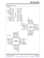
Page 4: ...1 T1OSI CCP2 RC2 CCP1 RC3 SCK SCL RC4 SDI SDA RC5 SDO RC6 TX CK 23 24 25 26 27 28 22 RA1 AN1 RA0 AN0 RB7 PGD RB6 PGC RB5 RB4 10 11 8 9 12 13 14 28 Pin QFN PIC16F873A PIC16F876A RB2 RB1 RC0 T1OSO T1CKI...

Page 5: ...AN5 OSC1 CLKI OSC2 CLKO RC0 T1OSO T1CK1 NC RE1 WR AN6 RE2 CS AN7 VDD VSS RB3 PGM RB2 RB1 RB0 INT VDD VSS RD7 PSP7 RD6 PSP6 RD5 PSP5 RD4 PSP4 RA3 AN3 V REF RA2 AN2 V REF CV REF RA1 AN1 RA0 AN0 MCLR V...

Page 6: ...or comments regarding this publication please contact the Marketing Communications Department via E mail at docerrors mail microchip com or fax the Reader Response Form in the back of this data sheet...

Page 7: ...33023 which may be obtained from your local Microchip Sales Represen tative or downloaded from the Microchip web site The Reference Manual should be considered a complemen tary document to this data s...

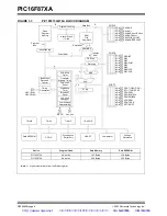
Page 8: ...PORTC RA4 T0CKI C1OUT RA5 AN4 SS C2OUT RB0 INT RC0 T1OSO T1CKI RC1 T1OSI CCP2 RC2 CCP1 RC3 SCK SCL RC4 SDI SDA RC5 SDO RC6 TX CK RC7 RX DT 8 8 Brown out Reset Note 1 Higher order bits are from the St...

Page 9: ...OSI CCP2 RC2 CCP1 RC3 SCK SCL RC4 SDI SDA RC5 SDO RC6 TX CK RC7 RX DT RE0 RD AN5 RE1 WR AN6 RE2 CS AN7 8 8 Brown out Reset Note 1 Higher order bits are from the Status register RA3 AN3 VREF RA2 AN2 VR...

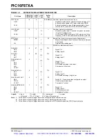
Page 10: ...age input PORTA is a bidirectional I O port RA0 AN0 RA0 AN0 2 27 I O I TTL Digital I O Analog input 0 RA1 AN1 RA1 AN1 3 28 I O I TTL Digital I O Analog input 1 RA2 AN2 VREF CVREF RA2 AN2 VREF CVREF 4...

Page 11: ...Compare1 output PWM1 output RC3 SCK SCL RC3 SCK SCL 14 11 I O I O I O ST Digital I O Synchronous serial clock input output for SPI mode Synchronous serial clock input output for I2 C mode RC4 SDI SDA...

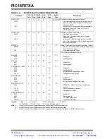
Page 12: ...e input PORTA is a bidirectional I O port RA0 AN0 RA0 AN0 2 3 19 19 I O I TTL Digital I O Analog input 0 RA1 AN1 RA1 AN1 3 4 20 20 I O I TTL Digital I O Analog input 1 RA2 AN2 VREF CVREF RA2 AN2 VREF...

Page 13: ...Digital I O In circuit debugger and ICSP programming clock RB7 PGD RB7 PGD 40 44 17 17 I O I O TTL ST 2 Digital I O In circuit debugger and ICSP programming data TABLE 1 3 PIC16F874A 877A PINOUT DESCR...

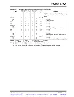
Page 14: ...tal I O SPI data in I2C data I O RC5 SDO RC5 SDO 24 26 43 43 I O O ST Digital I O SPI data out RC6 TX CK RC6 TX CK 25 27 44 44 I O O I O ST Digital I O USART asynchronous transmit USART1 synchronous c...

Page 15: ...Digital I O Read control for Parallel Slave Port Analog input 5 RE1 WR AN6 RE1 WR AN6 9 10 26 26 I O I I ST TTL 3 Digital I O Write control for Parallel Slave Port Analog input 6 RE2 CS AN7 RE2 CS AN...

Page 16: ...PIC16F87XA DS39582B page 14 2003 Microchip Technology Inc NOTES http www xinpian net IC 010 62245566 13810019655...

Page 17: ...an 8K word x 14 bit program memory space The PIC16F876A 877A devices have 8K words x 14 bits of Flash program memory while PIC16F873A 874A devices have 4K words x 14 bits Accessing a location above t...

Page 18: ...al Function Regis ters are General Purpose Registers implemented as static RAM All implemented banks contain Special Function Registers Some frequently used Special Function Registers from one bank ma...

Page 19: ...ct addr PCL STATUS FSR PCLATH INTCON PCL STATUS FSR PCLATH INTCON 100h 101h 102h 103h 104h 105h 106h 107h 108h 109h 10Ah 10Bh 10Ch 10Dh 10Eh 10Fh 110h 111h 112h 113h 114h 115h 116h 117h 118h 119h 11Ah...

Page 20: ...PCLATH INTCON 100h 101h 102h 103h 104h 105h 106h 107h 108h 109h 10Ah 10Bh 180h 181h 182h 183h 184h 185h 186h 187h 188h 189h 18Ah 18Bh 17Fh 1FFh Bank 2 Bank 3 Indirect addr PORTD 1 PORTE 1 TRISD 1 ADR...

Page 21: ...28 150 0Eh TMR1L Holding Register for the Least Significant Byte of the 16 bit TMR1 Register xxxx xxxx 60 150 0Fh TMR1H Holding Register for the Most Significant Byte of the 16 bit TMR1 Register xxxx...

Page 22: ...h SSPADD Synchronous Serial Port I2 C mode Address Register 0000 0000 79 151 94h SSPSTAT SMP CKE D A P S R W UA BF 0000 0000 79 151 95h Unimplemented 96h Unimplemented 97h Unimplemented 98h TXSTA CSRC...

Page 23: ...000 30 150 183h 3 STATUS IRP RP1 RP0 TO PD Z DC C 0001 1xxx 22 150 184h 3 FSR Indirect Data Memory Address Pointer xxxx xxxx 31 150 185h Unimplemented 186h TRISB PORTB Data Direction Register 1111 111...

Page 24: ...W x R W x R W x IRP RP1 RP0 TO PD Z DC C bit 7 bit 0 bit 7 IRP Register Bank Select bit used for indirect addressing 1 Bank 2 3 100h 1FFh 0 Bank 0 1 00h FFh bit 6 5 RP1 RP0 Register Bank Select bits u...

Page 25: ...of RB0 INT pin 0 Interrupt on falling edge of RB0 INT pin bit 5 T0CS TMR0 Clock Source Select bit 1 Transition on RA4 T0CKI pin 0 Internal instruction cycle clock CLKO bit 4 T0SE TMR0 Source Edge Sel...

Page 26: ...MR0 Overflow Interrupt Enable bit 1 Enables the TMR0 interrupt 0 Disables the TMR0 interrupt bit 4 INTE RB0 INT External Interrupt Enable bit 1 Enables the RB0 INT external interrupt 0 Disables the RB...

Page 27: ...verter interrupt bit 5 RCIE USART Receive Interrupt Enable bit 1 Enables the USART receive interrupt 0 Disables the USART receive interrupt bit 4 TXIE USART Transmit Interrupt Enable bit 1 Enables the...

Page 28: ...ust be cleared in software before returning from the Interrupt Service Routine The conditions that will set this bit are SPI A transmission reception has taken place I2C Slave A transmission reception...

Page 29: ...6 CMIE Comparator Interrupt Enable bit 1 Enables the comparator interrupt 0 Disable the comparator interrupt bit 5 Unimplemented Read as 0 bit 4 EEIE EEPROM Write Operation Interrupt Enable bit 1 Enab...

Page 30: ...ust be cleared in software 0 The comparator input has not changed bit 5 Unimplemented Read as 0 bit 4 EEIF EEPROM Write Operation Interrupt Flag bit 1 The write operation completed must be cleared in...

Page 31: ...care and is not predictable if the brown out circuit is dis abled by clearing the BODEN bit in the configuration word U 0 U 0 U 0 U 0 U 0 U 0 R W 0 R W 1 POR BOR bit 7 bit 0 bit 7 2 Unimplemented Read...

Page 32: ...16F87XA devices are capable of addressing a continuous 8K word block of program memory The CALL and GOTO instructions provide only 11 bits of address to allow branching within any 2K program memory pa...

Page 33: ...dress is obtained by concatenating the 8 bit FSR register and the IRP bit Status 7 as shown in Figure 2 6 A simple program to clear RAM locations 20h 2Fh using indirect addressing is shown in Example...

Page 34: ...PIC16F87XA DS39582B page 32 2003 Microchip Technology Inc NOTES http www xinpian net IC 010 62245566 13810019655...

Page 35: ...y are allowed When code protected the device programmer can no longer access data or program memory this does NOT inhibit internal reads or writes 3 1 EEADR and EEADRH The EEADRH EEADR register pair c...

Page 36: ...set during normal operation 0 The write operation completed bit 2 WREN EEPROM Write Enable bit 1 Allows write cycles 0 Inhibits write to the EEPROM bit 1 WR Write Control bit 1 Initiates a write cycle...

Page 37: ...write cycle the WR bit is cleared in hardware and the EE Write Complete Interrupt Flag bit EEIF is set The user can either enable this interrupt or poll this bit EEIF must be cleared by software The...

Page 38: ...refore it can be read as two bytes in the following instructions EEDATA and EEDATH registers will hold this value until another read or until it is written to by the user during a write operation EXAM...

Page 39: ...ry the EEADR and EEADRH must point to the last location in the four word block EEADR 1 0 11 Then the following sequence of events must be executed 1 Set the EEPGD control bit EECON1 7 2 Write 55h then...

Page 40: ...er MOVWF EEDATA INCF FSR F Next byte MOVF INDF W Load second data byte into upper MOVWF EEDATH INCF FSR F BSF STATUS RP0 Bank 3 BSF EECON1 EEPGD Point to program memory BSF EECON1 WREN Enable writes B...

Page 41: ...device may be selectively inhibited to regions of the memory depend ing on the setting of bits WR1 WR0 of the configuration word see Section 14 1 Configuration Bits for addi tional information Externa...

Page 42: ...PIC16F87XA DS39582B page 40 2003 Microchip Technology Inc NOTES http www xinpian net IC 010 62245566 13810019655...

Page 43: ...tt Trigger input and an open drain output All other PORTA pins have TTL input levels and full CMOS output drivers Other PORTA pins are multiplexed with analog inputs and the analog VREF input for both...

Page 44: ...O pin 1 TMR0 Clock Input Q D Q CK Q D Q CK EN Q D EN C1OUT Note 1 I O pin has protection diodes to VSS only CMCON 2 0 x01 or 011 1 0 Data Bus WR PORTA WR TRISA RD PORTA Data Latch TRIS Latch RD TRISA...

Page 45: ...serial port or comparator output Legend TTL TTL input ST Schmitt Trigger input Address Name Bit 7 Bit 6 Bit 5 Bit 4 Bit 3 Bit 2 Bit 1 Bit 0 Value on POR BOR Value on all other Resets 05h PORTA RA5 RA4...

Page 46: ...ear the interrupt in the following manner a Any read or write of PORTB This will end the mismatch condition b Clear flag bit RBIF A mismatch condition will continue to set flag bit RBIF Reading PORTB...

Page 47: ...p Serial programming clock RB7 PGD bit 7 TTL ST 2 Input output pin with interrupt on change or in circuit debugger pin Internal software programmable weak pull up Serial programming data Legend TTL TT...

Page 48: ...tions BSF BCF XORWF with TRISC as the destination should be avoided The user should refer to the corresponding peripheral section for the correct TRIS bit settings FIGURE 4 6 PORTC BLOCK DIAGRAM PERIP...

Page 49: ...erial clock for both SPI and I2 C modes RC4 SDI SDA bit 4 ST RC4 can also be the SPI data in SPI mode or data I O I2 C mode RC5 SDO bit 5 ST Input output port pin or Synchronous Serial Port data outpu...

Page 50: ...ort pin or Parallel Slave Port bit 1 RD2 PSP2 bit2 ST TTL 1 Input output port pin or Parallel Slave Port bit 2 RD3 PSP3 bit 3 ST TTL 1 Input output port pin or Parallel Slave Port bit 3 RD4 PSP4 bit 4...

Page 51: ...AGRAM IN I O PORT MODE TABLE 4 9 PORTE FUNCTIONS Note PORTE and TRISE are not implemented on the 28 pin devices Note On a Power on Reset these pins are configured as analog inputs and read as 0 Data B...

Page 52: ...the CPU 0 No word has been received bit 6 OBF Output Buffer Full Status bit 1 The output buffer still holds a previously written word 0 The output buffer has been read bit 5 IBOV Input Buffer Overflo...

Page 53: ...the Input Buffer Full IBF status flag bit TRISE 7 is set on the Q4 clock cycle following the next Q2 cycle to signal the write is complete Figure 4 11 The interrupt flag bit PSPIF PIR1 7 is also set...

Page 54: ...h PORTD Port Data Latch when written Port pins when read xxxx xxxx uuuu uuuu 09h PORTE RE2 RE1 RE0 xxx uuu 89h TRISE IBF OBF IBOV PSPMODE PORTE Data Direction bits 0000 111 0000 111 0Ch PIR1 PSPIF 1 A...

Page 55: ...determined by the Timer0 Source Edge Select bit T0SE OPTION_REG 4 Clearing bit T0SE selects the ris ing edge Restrictions on the external clock input are discussed in detail in Section 5 2 Using Timer...

Page 56: ...escaler along with the Watchdog Timer The prescaler is not readable or writable REGISTER 5 1 OPTION_REG REGISTER Note Writing to TMR0 when the prescaler is assigned to Timer0 will clear the prescaler...

Page 57: ...all other Resets 01h 101h TMR0 Timer0 Module Register xxxx xxxx uuuu uuuu 0Bh 8Bh 10Bh 18Bh INTCON GIE PEIE TMR0IE INTE RBIE TMR0IF INTF RBIF 0000 000x 0000 000u 81h 181h OPTION_REG RBPU INTEDG T0CS...

Page 58: ...PIC16F87XA DS39582B page 56 2003 Microchip Technology Inc NOTES http www xinpian net IC 010 62245566 13810019655...

Page 59: ...1OSO T1CKI pins become inputs That is the TRISC 1 0 value is ignored and these pins read as 0 Additional information on timer modules is available in the PICmicro Mid Range MCU Family Reference Manual...

Page 60: ...g edge of clock input on pin RC1 T1OSI CCP2 when bit T1OSCEN is set or on pin RC0 T1OSO T1CKI when bit T1OSCEN is cleared If T1SYNC is cleared then the external clock input is synchronized with intern...

Page 61: ...ol bit T1OSCEN T1CON 3 The oscil lator is a low power oscillator rated up to 200 kHz It will continue to run during Sleep It is primarily intended for use with a 32 kHz crystal Table 6 1 shows the cap...

Page 62: ...t 0 Value on POR BOR Value on all other Resets 0Bh 8Bh 10Bh 18Bh INTCON GIE PEIE TMR0IE INTE RBIE TMR0IF INTF RBIF 0000 000x 0000 000u 0Ch PIR1 PSPIF 1 ADIF RCIF TXIF SSPIF CCP1IF TMR2IF TMR1IF 0000 0...

Page 63: ...ows the Timer2 Control register Additional information on timer modules is available in the PICmicro Mid Range MCU Family Reference Manual DS33023 FIGURE 7 1 TIMER2 BLOCK DIAGRAM REGISTER 7 1 T2CON TI...

Page 64: ...it 5 Bit 4 Bit 3 Bit 2 Bit 1 Bit 0 Value on POR BOR Value on all other Resets 0Bh 8Bh 10Bh 18Bh INTCON GIE PEIE TMR0IE INTE RBIE TMR0IF INTF RBIF 0000 000x 0000 000u 0Ch PIR1 PSPIF 1 ADIF RCIF TXIF SS...

Page 65: ...1 CCP2 Module Capture Compare PWM Register 2 CCPR2 is com prised of two 8 bit registers CCPR2L low byte and CCPR2H high byte The CCP2CON register controls the operation of CCP2 The special event trigg...

Page 66: ...0100 Capture mode every falling edge 0101 Capture mode every rising edge 0110 Capture mode every 4th rising edge 0111 Capture mode every 16th rising edge 1000 Compare mode set output on match CCPxIF...

Page 67: ...false capture interrupt may be generated The user should keep bit CCP1IE PIE1 2 clear to avoid false interrupts and should clear the flag bit CCP1IF following any such change in operating mode 8 1 4...

Page 68: ...ected The CCPIF bit is set causing a CCP interrupt if enabled 8 2 4 SPECIAL EVENT TRIGGER In this mode an internal hardware trigger is generated which may be used to initiate an action The special eve...

Page 69: ...CP1CON 5 4 The following equation is used to calculate the PWM duty cycle in time PWM Duty Cycle CCPR1L CCP1CON 5 4 TOSC TMR2 Prescale Value CCPR1L and CCP1CON 5 4 can be written to at any time but th...

Page 70: ...000u 0Ch PIR1 PSPIF 1 ADIF RCIF TXIF SSPIF CCP1IF TMR2IF TMR1IF 0000 0000 0000 0000 0Dh PIR2 CCP2IF 0 0 8Ch PIE1 PSPIE 1 ADIE RCIE TXIE SSPIE CCP1IE TMR2IE TMR1IE 0000 0000 0000 0000 8Dh PIE2 CCP2IE...

Page 71: ...0 0000 0000 0000 92h PR2 Timer2 Module s Period Register 1111 1111 1111 1111 12h T2CON TOUTPS3 TOUTPS2 TOUTPS1 TOUTPS0 TMR2ON T2CKPS1 T2CKPS0 000 0000 000 0000 15h CCPR1L Capture Compare PWM Register...

Page 72: ...PIC16F87XA DS39582B page 70 2003 Microchip Technology Inc NOTES http www xinpian net IC 010 62245566 13810019655...

Page 73: ...ansmitted and received simultaneously All four modes of SPI are supported To accomplish communication typically three pins are used Serial Data Out SDO RC5 SDO Serial Data In SDI RC4 SDI SDA Serial Cl...

Page 74: ...PSTAT MSSP STATUS REGISTER SPI MODE ADDRESS 94h R W 0 R W 0 R 0 R 0 R 0 R 0 R 0 R 0 SMP CKE D A P S R W UA BF bit 7 bit 0 bit 7 SMP Sample bit SPI Master mode 1 Input data sampled at end of data outpu...

Page 75: ...on is initiated by writing to the SSPBUF register bit 5 SSPEN Synchronous Serial Port Enable bit 1 Enables serial port and configures SCK SDO SDI and SS as serial port pins 0 Disables serial port and...

Page 76: ...etect bit WCOL SSPCON 7 will be set User software must clear the WCOL bit so that it can be determined if the follow ing write s to the SSPBUF register completed successfully When the application soft...

Page 77: ...ite value 9 3 4 TYPICAL CONNECTION Figure 9 2 shows a typical connection between two microcontrollers The master controller Processor 1 initiates the data transfer by sending the SCK signal Data is sh...

Page 78: ...PCON 4 This then would give waveforms for SPI communication as shown in Figure 9 3 Figure 9 5 and Figure 9 6 where the MSB is transmitted first In Master mode the SPI clock rate bit rate is user progr...

Page 79: ...pin is no longer driven even if in the middle of a transmitted byte and becomes a floating output External pull up pull down resistors may be desirable depending on the application When the SPI modul...

Page 80: ...bit 6 bit 5 bit 4 bit 3 bit 2 bit 1 bit 0 SSPIF Interrupt SMP 0 CKE 0 CKE 0 SMP 0 Write to SSPBUF SSPSR to SSPBUF SS Flag Optional Next Q4 Cycle after Q2 SCK CKP 1 SCK CKP 0 Input Sample SDI bit 7 bit...

Page 81: ...re is also a SMP bit which controls when the data is sampled TABLE 9 2 REGISTERS ASSOCIATED WITH SPI OPERATION Standard SPI Mode Terminology Control Bits State CKP CKE 0 0 0 1 0 1 0 0 1 0 1 1 1 1 1 0...

Page 82: ...SSPCON2 and SSPSTAT are the control and status registers in I2 C mode operation The SSPCON and SSPCON2 registers are readable and writable The lower six bits of the SSPSTAT are read only The upper two...

Page 83: ...s not detected last Note This bit is cleared on Reset and when SSPEN is cleared bit 2 R W Read Write bit information I2 C mode only In Slave mode 1 Read 0 Write Note This bit holds the R W bit informa...

Page 84: ...5 SSPEN Synchronous Serial Port Enable bit 1 Enables the serial port and configures the SDA and SCL pins as the serial port pins 0 Disables the serial port and configures these pins as I O port pins N...

Page 85: ...RCEN Receive Enable bit Master mode only 1 Enables Receive mode for I2 C 0 Receive Idle bit 2 PEN Stop Condition Enable bit Master mode only 1 Initiate Stop condition on SDA and SCL pins Automatically...

Page 86: ...clock input must have a minimum high and low for proper operation The high and low times of the I2 C specification as well as the requirement of the MSSP module are shown in timing parameter 100 and...

Page 87: ...pin RC3 SCK SCL is held low regard less of SEN see Section 9 4 4 Clock Stretching for more detail By stretching the clock the master will be unable to assert another clock pulse until the slave is do...

Page 88: ...2 3 4 5 6 7 8 9 1 2 3 4 5 7 8 9 P A7 A6 A5 A4 A3 A2 A1 D7 D6 D5 D4 D3 D2 D1 D0 D7 D6 D5 D4 D3 D1 D0 ACK Receiving Data ACK Receiving Data R W 0 ACK Receiving Address Cleared in software SSPBUF is read...

Page 89: ...8 9 SSPBUF is written in software Cleared in software SCL held low while CPU responds to SSPIF From SSPIF ISR Data in sampled S ACK Transmitting Data R W 1 ACK Receiving Address A7 D7 9 1 D6 D5 D4 D3...

Page 90: ...UA SSPSTAT 1 Clock is held low until update of SSPADD has taken place UA is set indicating that the SSPADD needs to be updated UA is set indicating that SSPADD needs to be updated Cleared by hardware...

Page 91: ...needs to be updated UA is set indicating that SSPADD needs to be updated Cleared by hardware when SSPADD is updated with high byte of address SSPBUF is written with contents of SSPSR Dummy read of SSP...

Page 92: ...s occurs regardless of the state of the SEN bit The user s ISR must set the CKP bit before transmis sion is allowed to continue By holding the SCL line low the user has time to service the ISR and loa...

Page 93: ...C master device has already asserted the SCL line The SCL output will remain low until the CKP bit is set and all other devices on the I2 C bus have deasserted SCL This ensures that a write to the CKP...

Page 94: ...SSPBUF is read Bus master terminates transfer SSPOV is set because SSPBUF is still full ACK is not sent D2 6 PIR1 3 CKP CKP written to 1 in If BF is cleared prior to the falling edge of the 9th clock...

Page 95: ...en SSPADD is updated with high byte of address after falling edge SSPBUF is written with contents of SSPSR Dummy read of SSPBUF to clear BF flag ACK CKP 1 2 3 4 5 7 8 9 D7 D6 D5 D4 D3 D1 D0 Receive Da...

Page 96: ...ag bit is set eighth bit and on the falling edge of the ninth bit ACK bit the SSPIF interrupt flag bit is set When the interrupt is serviced the source for the inter rupt can be checked by reading the...

Page 97: ...of a received byte of data 6 Generate a Stop condition on SDA and SCL The following events will cause SSP Interrupt Flag bit SSPIF to be set SSP interrupt if enabled Start condition Stop condition Da...

Page 98: ...d an Acknowledge bit is transmit ted Start and Stop conditions indicate the beginning and end of transmission The baud rate generator used for the SPI mode opera tion is used to set the SCL clock freq...

Page 99: ...ting and the SCL pin will remain in its last state Table 9 3 demonstrates clock rates based on instruction cycles and the BRG value loaded into SSPADD FIGURE 9 17 BAUD RATE GENERATOR BLOCK DIAGRAM TAB...

Page 100: ...Baud Rate Generator is reloaded with the contents of SSPADD 6 0 and begins counting This ensures that the SCL high time will always be at least one BRG rollover count in the event that the clock is h...

Page 101: ...leaving the SDA line held low and the Start condition is complete 9 4 8 1 WCOL Status Flag If the user writes the SSPBUF when a Start sequence is in progress the WCOL is set and the contents of the bu...

Page 102: ...timed out Immediately following the SSPIF bit getting set the user may write the SSPBUF with the 7 bit address in 7 bit mode or the default first address in 10 bit mode After the first eight bits are...

Page 103: ...tor is turned off until another write to the SSPBUF takes place holding SCL low and allowing SDA to float 9 4 10 1 BF Status Flag In Transmit mode the BF bit SSPSTAT 0 is set when the CPU writes to SS...

Page 104: ...9 1 2 3 4 5 6 7 8 9 P Cleared in software service routine SSPBUF is written in software from SSP interrupt After Start condition SEN cleared by hardware S SSPBUF written with 7 bit address and R W St...

Page 105: ...LK Cleared in software start XMIT SEN 0 SSPOV SDA 0 SCL 1 while CPU SSPSTAT 0 ACK Last bit is shifted into SSPSR and contents are unloaded into SSPBUF Cleared in software Cleared in software Set SSPIF...

Page 106: ...of the ninth clock When the PEN bit is set the master will assert the SDA line low When the SDA line is sam pled low the Baud Rate Generator is reloaded and counts down to 0 When the Baud Rate Generat...

Page 107: ...sampled on the SDA pin 0 then a bus collision has taken place The master will set the Bus Collision Interrupt Flag BCLIF and reset the I2 C port to its Idle state Figure 9 25 If a transmit was in pro...

Page 108: ...the SDA pin is asserted low at the end of the BRG count The Baud Rate Generator is then reloaded and counts down to 0 and during this time if the SCL pin is sampled as 0 a bus collision does not occur...

Page 109: ...quence if SDA 1 SCL 1 TBRG TBRG SDA 0 SCL 1 BCLIF S SSPIF Interrupt cleared in software bus collision occurs Set BCLIF SCL 0 before BRG time out 0 0 0 0 SDA SCL SEN Set S Less than TBRG TBRG SDA 0 SCL...

Page 110: ...ion occurs because no two masters can assert SDA at exactly the same time If SCL goes from high to low before the BRG times out and SDA has not already been asserted a bus collision occurs In this cas...

Page 111: ...ith SSPADD 6 0 and counts down to 0 After the BRG times out SDA is sampled If SDA is sampled low a bus collision has occurred This is due to another master attempting to drive a data 0 Figure 9 31 If...

Page 112: ...PIC16F87XA DS39582B page 110 2003 Microchip Technology Inc NOTES http www xinpian net IC 010 62245566 13810019655...

Page 113: ...odule also has a multi processor communication capability using 9 bit address detection REGISTER 10 1 TXSTA TRANSMIT STATUS AND CONTROL REGISTER ADDRESS 98h R W 0 R W 0 R W 0 R W 0 U 0 R W 0 R 1 R W 0...

Page 114: ...continuous receive 0 Disables continuous receive Synchronous mode 1 Enables continuous receive until enable bit CREN is cleared CREN overrides SREN 0 Disables continuous receive bit 3 ADDEN Address D...

Page 115: ...e baud rate error in some cases Writing a new value to the SPBRG register causes the BRG timer to be reset or cleared This ensures the BRG does not wait for a timer overflow before outputting the new...

Page 116: ...20 833 8 51 2 19 2 0 2 28 8 31 250 8 51 1 28 8 0 1 33 6 57 6 62 500 8 51 0 57 6 0 0 HIGH 0 244 255 0 225 255 LOW 62 500 0 57 6 0 TABLE 10 4 BAUD RATES FOR ASYNCHRONOUS MODE BRGH 1 BAUD RATE K FOSC 20...

Page 117: ...soft ware It will reset only when new data is loaded into the TXREG register While flag bit TXIF indicates the status of the TXREG register another bit TRMT TXSTA 1 shows the status of the TSR registe...

Page 118: ...10Bh 18Bh INTCON GIE PEIE TMR0IE INTE RBIE TMR0IF INTF R0IF 0000 000x 0000 000u 0Ch PIR1 PSPIF 1 ADIF RCIF TXIF SSPIF CCP1IF TMR2IF TMR1IF 0000 0000 0000 0000 18h RCSTA SPEN RX9 SREN CREN FERR OERR R...

Page 119: ...third byte to begin shifting to the RSR register On the detection of the Stop bit of the third byte if the RCREG register is still full the Overrun Error bit OERR RCSTA 1 will be set The word in the...

Page 120: ...S RECEPTION Start bit bit 7 8 bit 1 bit 0 bit 7 8 bit 0 Stop bit Start bit Start bit bit 7 8 Stop bit RX pin Reg Rcv Buffer Reg Rcv Shift Read Rcv Buffer Reg RCREG RCIF Interrupt Flag OERR bit CREN Wo...

Page 121: ...ated if enable bit RCIE was set Read the RCSTA register to get the ninth bit and determine if any error occurred during reception Read the 8 bit received data by reading the RCREG register to determin...

Page 122: ...yte The data byte is not read into the RCREG Receive Buffer because ADDEN was not updated and still 0 pin Address Name Bit 7 Bit 6 Bit 5 Bit 4 Bit 3 Bit 2 Bit 1 Bit 0 Value on POR BOR Value on all oth...

Page 123: ...he TXREG register and then setting bit TXEN Figure 10 10 This is advantageous when slow baud rates are selected since the BRG is kept in Reset when bits TXEN CREN and SREN are clear Setting enable bit...

Page 124: ...MR1IE 0000 0000 0000 0000 98h TXSTA CSRC TX9 TXEN SYNC BRGH TRMT TX9D 0000 010 0000 010 99h SPBRG Baud Rate Generator Register 0000 0000 0000 0000 Legend x unknown unimplemented read as 0 Shaded cells...

Page 125: ...to read the RCSTA register before reading RCREG in order not to lose the old RX9D information When setting up a Synchronous Master Reception 1 Initialize the SPBRG register for the appropriate baud r...

Page 126: ...ag bit TXIF will now be set e If enable bit TXIE is set the interrupt will wake the chip from Sleep and if the global interrupt is enabled the program will branch to the interrupt vector 0004h When se...

Page 127: ...OCIATED WITH SYNCHRONOUS SLAVE RECEPTION Address Name Bit 7 Bit 6 Bit 5 Bit 4 Bit 3 Bit 2 Bit 1 Bit 0 Value on POR BOR Value on all other Resets 0Bh 8Bh 10Bh 18Bh INTCON GIE PEIE TMR0IE INTE RBIE TMR0...

Page 128: ...PIC16F87XA DS39582B page 126 2003 Microchip Technology Inc NOTES http www xinpian net IC 010 62245566 13810019655...

Page 129: ...3023 REGISTER 11 1 ADCON0 REGISTER ADDRESS 1Fh R W 0 R W 0 R W 0 R W 0 R W 0 R W 0 U 0 R W 0 ADCS1 ADCS0 CHS2 CHS1 CHS0 GO DONE ADON bit 7 bit 0 bit 7 6 ADCS1 ADCS0 A D Conversion Clock Select bits AD...

Page 130: ...an analog input ADCON1 ADCS2 ADCON0 ADCS1 ADCS0 Clock Conversion 0 00 FOSC 2 0 01 FOSC 8 0 10 FOSC 32 0 11 FRC clock derived from the internal A D RC oscillator 1 00 FOSC 4 1 01 FOSC 16 1 10 FOSC 64 1...

Page 131: ...ure analog pins voltage reference and digital I O ADCON1 Select A D input channel ADCON0 Select A D conversion clock ADCON0 Turn on A D module ADCON0 2 Configure A D interrupt if desired Clear ADIF bi...

Page 132: ...D to meet its specified resolution To calculate the minimum acquisition time TACQ see the PICmicro Mid Range MCU Family Reference Manual DS33023 EQUATION 11 1 ACQUISITION TIME FIGURE 11 2 ANALOG INPU...

Page 133: ...ion is independent of the state of the CHS2 CHS0 bits and the TRIS bits TABLE 11 1 TAD vs MAXIMUM DEVICE OPERATING FREQUENCIES STANDARD DEVICES F Note 1 When reading the port register any pin configur...

Page 134: ...ersion This register pair is 16 bits wide The A D module gives the flexibility to left or right justify the 10 bit result in the 16 bit result register The A D Format Select bit ADFM controls this jus...

Page 135: ...egisters is not modified for a Power on Reset The ADRESH ADRESL registers will contain unknown data after a Power on Reset TABLE 11 2 REGISTERS BITS ASSOCIATED WITH A D Note For the A D module to oper...

Page 136: ...PIC16F87XA DS39582B page 134 2003 Microchip Technology Inc NOTES http www xinpian net IC 010 62245566 13810019655...

Page 137: ...t 0 bit 7 C2OUT Comparator 2 Output bit When C2INV 0 1 C2 VIN C2 VIN 0 C2 VIN C2 VIN When C2INV 1 1 C2 VIN C2 VIN 0 C2 VIN C2 VIN bit 6 C1OUT Comparator 1 Output bit When C1INV 0 1 C1 VIN C1 VIN 0 C1...

Page 138: ...OUT A A C1 RA0 AN0 VIN VIN RA3 AN3 C1OUT Two Common Reference Comparators A A CM2 CM0 100 C2 RA1 AN1 VIN VIN RA2 AN2 C2OUT A D C2 RA1 AN1 VIN VIN RA2 AN2 Off Read as 0 One Independent Comparator with...

Page 139: ...are in mode CM 2 0 110 Figure 12 1 In this mode the internal voltage reference is applied to the VIN pin of both comparators 12 4 Comparator Response Time Response time is the minimum time after sele...

Page 140: ...interrupt In addition the GIE bit must also be set If any of these bits are clear the interrupt is not enabled though the CMIF bit will still be set if an interrupt condition occurs The user in the I...

Page 141: ...the Comparator Off mode CM 2 0 111 This ensures compatibility to the PIC16F87X devices 12 9 Analog Input Connection Considerations A simplified circuit for an analog input is shown in Figure 12 4 Sin...

Page 142: ...CVRR CVR3 CVR2 CVR1 CVR0 000 0000 000 0000 0Bh 8Bh 10Bh 18Bh INTCON GIE GIEH PEIE GIEL TMR0IE INTIE RBIE TMR0IF INTIF RBIF 0000 000x 0000 000u 0Dh PIR2 CMIF BCLIF LVDIF TMR3IF CCP2IF 0 0000 0 0000 8Dh...

Page 143: ...RA2 AN2 VREF CVREF pin This can be used as a simple D A function by the user if a very high impedance load is used The primary purpose of this function is to provide a test path for testing the refer...

Page 144: ...o Comparator CVROE RA2 AN2 VREF CVREF VDD CVR2 CVR1 Address Name Bit 7 Bit 6 Bit 5 Bit 4 Bit 3 Bit 2 Bit 1 Bit 0 Value on POR Value on all other Resets 9Dh CVRCON CVREN CVROE CVRR CVR3 CVR2 CVR1 CVR0...

Page 145: ...ay of 72 ms nomi nal on power up only It is designed to keep the part in Reset while the power supply stabilizes With these two timers on chip most applications need no external Reset circuitry Sleep...

Page 146: ...all program memory may be written to by EECON control 10 0000h to 00FFh write protected 0100h to 0FFFh may be written to by EECON control 01 0000h to 03FFh write protected 0400h to 0FFFh may be writt...

Page 147: ...ve the OSC1 CLKI pin Figure 14 2 FIGURE 14 1 CRYSTAL CERAMIC RESONATOROPERATION HS XT OR LP OSC CONFIGURATION FIGURE 14 2 EXTERNAL CLOCK INPUT OPERATION HS XT OR LP OSC CONFIGURATION TABLE 14 1 CERAMI...

Page 148: ...kHz 33 pF 33 pF 200 kHz 15 pF 15 pF XT 200 kHz 47 68 pF 47 68 pF 1 MHz 15 pF 15 pF 4 MHz 15 pF 15 pF HS 4 MHz 15 pF 15 pF 8 MHz 15 33 pF 15 33 pF 20 MHz 15 33 pF 15 33 pF These values are for design...

Page 149: ...is viewed as the resumption of normal operation The TO and PD bits are set or cleared differ ently in different Reset situations as indicated in Table 14 4 These bits are used in software to deter min...

Page 150: ...parameter 33 14 7 Oscillator Start up Timer OST The Oscillator Start up Timer OST provides a delay of 1024 oscillator cycles from OSC1 input after the PWRT delay is over if PWRT is enabled This helps...

Page 151: ...cillator Configuration Power up Brown out Wake up from Sleep PWRTE 0 PWRTE 1 XT HS LP 72 ms 1024 TOSC 1024 TOSC 72 ms 1024 TOSC 1024 TOSC RC 72 ms 72 ms POR BOR TO PD Condition 0 x 1 1 Power on Reset...

Page 152: ...000 0000 000 0000 uuu uuuu SSPBUF 73A 74A 76A 77A xxxx xxxx uuuu uuuu uuuu uuuu SSPCON 73A 74A 76A 77A 0000 0000 0000 0000 uuuu uuuu CCPR1L 73A 74A 76A 77A xxxx xxxx uuuu uuuu uuuu uuuu CCPR1H 73A 74...

Page 153: ...uu uuuu ADCON1 73A 74A 76A 77A 00 0000 00 0000 uu uuuu EEDATA 73A 74A 76A 77A xxxx xxxx uuuu uuuu uuuu uuuu EEADR 73A 74A 76A 77A xxxx xxxx uuuu uuuu uuuu uuuu EEDATH 73A 74A 76A 77A xxxx xxxx uuuu uu...

Page 154: ...MCLR NOT TIED TO VDD CASE 2 FIGURE 14 9 SLOW RISE TIME MCLR TIED TO VDD VIA RC NETWORK TPWRT TOST VDD MCLR Internal POR PWRT Time out OST Time out Internal Reset VDD MCLR Internal POR PWRT Time out O...

Page 155: ...PIE2 and the peripheral interrupt enable bit is contained in Special Function Register INTCON When an interrupt is responded to the GIE bit is cleared to disable any further interrupt the return addre...

Page 156: ...ypically users may wish to save key reg isters during an interrupt i e W register and Status register This will have to be implemented in software For the PIC16F873A 874A devices the register W_TEMP m...

Page 157: ...s under parameter 31 Values for the WDT prescaler actually a postscaler but shared with the Timer0 prescaler may be assigned using the OPTION_REG register FIGURE 14 11 WATCHDOG TIMER BLOCK DIAGRAM TAB...

Page 158: ...or receive in Slave mode SPI I2 C 7 USART RX or TX Synchronous Slave mode 8 A D conversion when A D clock source is RC 9 EEPROM write operation completion 10 Comparator output changes state Other peri...

Page 159: ...s 2000h 2003h are designated as ID locations where the user can store checksum or other code identification numbers These locations are not accessible during normal execution but are readable and writ...

Page 160: ...is set The LVP bit defaults to on 1 from the factory If Low Voltage Programming mode is not used the LVP bit can be programmed to a 0 and RB3 PGM becomes a digital I O pin However the LVP bit may onl...

Page 161: ...ion When this occurs the execution takes two instruction cycles with the second cycle executed as a NOP All instruction examples use the format 0xhh to represent a hexadecimal number where h signifies...

Page 162: ...11bb bfff bfff bfff bfff ffff ffff ffff ffff 1 2 1 2 3 3 LITERAL AND CONTROL OPERATIONS ADDLW ANDLW CALL CLRWDT GOTO IORLW MOVLW RETFIE RETLW RETURN SLEEP SUBLW XORLW k k k k k k k k k Add Literal and...

Page 163: ...s Affected Z Description AND the W register with register f If d is 0 the result is stored in the W register If d is 1 the result is stored back in register f BCF Bit Clear f Syntax label BCF f b Oper...

Page 164: ...ed Z Description W register is cleared Zero bit Z is set CLRWDT Clear Watchdog Timer Syntax label CLRWDT Operands None Operation 00h WDT 0 WDT prescaler 1 TO 1 PD Status Affected TO PD Description CLR...

Page 165: ...contents of register f are incremented If d is 0 the result is placed in the W register If d is 1 the result is placed back in register f INCFSZ Increment f Skip if 0 Syntax label INCFSZ f d Operands...

Page 166: ...ight through the Carry flag If d is 0 the result is placed in the W register If d is 1 the result is placed back in register f Register f C Register f C SLEEP Syntax label SLEEP Operands None Operatio...

Page 167: ...LW Exclusive OR Literal with W Syntax label XORLW k Operands 0 k 255 Operation W XOR k W Status Affected Z Description The contents of the W register are XOR ed with the eight bit literal k The result...

Page 168: ...PIC16F87XA DS39582B page 166 2003 Microchip Technology Inc NOTES http www xinpian net IC 010 62245566 13810019655...

Page 169: ...ls simulator programmer sold separately emulator sold separately in circuit debugger sold separately A full featured editor with color coded context A multiple project manager Customizable data window...

Page 170: ...time keeping and math functions trigonometric exponen tial and hyperbolic The compiler provides symbolic information for high level source debugging with the MPLAB IDE 16 6 MPLAB ASM30 Assembler Linke...

Page 171: ...real time emulation system with advanced features that are typically found on more expensive development tools The PC platform and Microsoft Windows 32 bit operating system were cho sen to best make t...

Page 172: ...irmware A prototype area extends the circuitry for additional application components Some of the features include an RS 232 interface a 2 x 16 LCD display a piezo speaker an on board temperature senso...

Page 173: ...tarter Kit includes the user s guide on CD ROM PICkit 1 tutorial software and code for vari ous applications Also included are MPLAB IDE Inte grated Development Environment software software and hardw...

Page 174: ...PIC16F87XA DS39582B page 172 2003 Microchip Technology Inc NOTES http www xinpian net IC 010 62245566 13810019655...

Page 175: ...ourced by PORTA PORTB and PORTE combined Note 3 200 mA Maximum current sunk by PORTC and PORTD combined Note 3 200 mA Maximum current sourced by PORTC and PORTD combined Note 3 200 mA Note 1 Power dis...

Page 176: ...L Frequency Voltage 6 0V 5 5V 4 5V 4 0V 2 0V 20 MHz 5 0V 3 5V 3 0V 2 5V PIC16F87XA Frequency Voltage 6 0V 5 5V 4 5V 4 0V 2 0V 5 0V 3 5V 3 0V 2 5V FMAX 6 0 MHz V VDDAPPMIN 2 0V 4 MHz Note 1 VDDAPPMIN i...

Page 177: ...herwise stated These parameters are for design guidance only and are not tested Note 1 This is the limit to which VDD can be lowered without losing RAM data 2 The supply current is mainly a function o...

Page 178: ...te 1 This is the limit to which VDD can be lowered without losing RAM data 2 The supply current is mainly a function of the operating voltage and frequency Other factors such as I O pin loading switch...

Page 179: ...otherwise stated These parameters are for design guidance only and are not tested Note 1 This is the limit to which VDD can be lowered without losing RAM data 2 The supply current is mainly a function...

Page 180: ...8 VDD VDD V For entire VDD range D042 MCLR 0 8 VDD VDD V D042A OSC1 in XT and LP modes 1 6V VDD V Note 1 OSC1 in HS mode 0 7 VDD VDD V D043 OSC1 in RC mode 0 9 VDD VDD V Ports RC3 and RC4 D044 with S...

Page 181: ...MIN 5 5 V Using EECON to read write VMIN min operating voltage D133 TPEW Erase Write cycle time 4 8 ms 17 2 DC Characteristics PIC16F873A 874A 876A 877A Industrial Extended PIC16LF873A 874A 876A 877A...

Page 182: ...r Mode Change to Output Valid 10 s These parameters are characterized but not tested Note 1 Response time measured with one comparator input at VDD 1 5 2 while the other input transitions from VSS to...

Page 183: ...in t0 T0CKI io I O port t1 T1CKI mc MCLR wr WR Uppercase letters and their meanings S F Fall P Period H High R Rise I Invalid High impedance V Valid L Low Z High impedance I2 C only AA output access...

Page 184: ...External Clock in OSC1 High or Low Time 100 ns XT oscillator 2 5 s LP oscillator 15 ns HS oscillator 4 TOSR TOSF External Clock in OSC1 Rise or Fall Time 25 ns XT oscillator 50 ns LP oscillator 15 ns...

Page 185: ...Hold after CLKO 0 ns Note 1 17 TOSH2IOV OSC1 Q1 cycle to Port Out Valid 100 255 ns 18 TOSH2IOI OSC1 Q2 cycle to Port Input Invalid I O in hold time Standard F 100 ns Extended LF 200 ns 19 TIOV2OSH Por...

Page 186: ...mbol Characteristic Min Typ Max Units Conditions 30 TMCL MCLR Pulse Width low 2 s VDD 5V 40 C to 85 C 31 TWDT Watchdog Timer Time out Period no prescaler 7 18 33 ms VDD 5V 40 C to 85 C 32 TOST Oscilla...

Page 187: ...s Extended LF 50 ns 46 TT1L T1CKI Low Time Synchronous Prescaler 1 0 5 TCY 20 ns Must also meet parameter 47 Synchronous Prescaler 2 4 8 Standard F 15 ns Extended LF 25 ns Asynchronous Standard F 30 n...

Page 188: ...5 TCY 20 ns With Prescaler Standard F 10 ns Extended LF 20 ns 51 TCCH CCP1 and CCP2 Input High Time No Prescaler 0 5 TCY 20 ns With Prescaler Standard F 10 ns Extended LF 20 ns 52 TCCP CCP1 and CCP2 I...

Page 189: ...ristic Min Typ Max Units Conditions 62 TDTV2WRH Data In Valid before WR or CS setup time 20 ns 63 TWRH2DTI WR or CS to Data in Invalid hold time Standard F 20 ns Extended LF 35 ns 64 TRDL2DTV RD and C...

Page 190: ...MP 1 SS SCK CKP 0 SCK CKP 1 SDO SDI 70 71 72 73 74 75 76 78 79 80 79 78 MSb LSb Bit 6 1 MSb In LSb In Bit 6 1 Note Refer to Figure 17 3 for load conditions SS SCK CKP 0 SCK CKP 1 SDO SDI 81 71 72 74 7...

Page 191: ...KP 0 SCK CKP 1 SDO SDI 70 71 72 73 74 75 76 77 78 79 80 79 78 SDI MSb LSb Bit 6 1 MSb In Bit 6 1 LSb In 83 Note Refer to Figure 17 3 for load conditions SS SCK CKP 0 SCK CKP 1 SDO SDI 70 71 72 82 SDI...

Page 192: ...all Time 10 25 ns 77 TSSH2DOZ SS to SDO Output High Impedance 10 50 ns 78 TSCR SCK Output Rise Time Master mode Standard F Extended LF 10 25 25 50 ns ns 79 TSCF SCK Output Fall Time Master mode 10 25...

Page 193: ...Start condition Setup time 400 kHz mode 600 91 THD STA Start condition 100 kHz mode 4000 ns After this period the first clock pulse is generated Hold time 400 kHz mode 600 92 TSU STO Stop condition 10...

Page 194: ...up Time 100 kHz mode 250 ns Note 2 400 kHz mode 100 ns 92 TSU STO Stop Condition Setup Time 100 kHz mode 4 7 s 400 kHz mode 0 6 s 109 TAA Output Valid from Clock 100 kHz mode 3500 ns Note 1 400 kHz mo...

Page 195: ...0 ns 121 TCKRF Clock Out Rise Time and Fall Time Master mode Standard F 45 ns Extended LF 50 ns 122 TDTRF Data Out Rise Time and Fall Time Standard F 45 ns Extended LF 50 ns Data in Typ column is at 5...

Page 196: ...of Analog Voltage Source 2 5 k Note 4 A40 IAD A D Conversion Current VDD PIC16F87XA 220 A Average current consumption when A D is on Note 1 PIC16LF87XA 90 A A50 IREF VREF Input Current Note 2 5 150 A...

Page 197: ...V Conversion Time not including S H time Note 1 12 TAD 132 TACQ Acquisition Time Note 2 10 40 s s The minimum time is the amplifier settling time This may be used if the new input volt age has not cha...

Page 198: ...PIC16F87XA DS39582B page 196 2003 Microchip Technology Inc NOTES http www xinpian net IC 010 62245566 13810019655...

Page 199: ...e provided for informational purposes only The performance characteristics listed herein are not tested or guaranteed In some graphs or tables the data presented may be outside the specified operating...

Page 200: ...0 3000 3500 4000 FOSC MHz I DD mA 2 0V 2 5V 3 0V 3 5V 4 0V 4 5V 5 0V 5 5V Typical statistical mean 25 C Maximum mean 3 40 C to 125 C Minimum mean 3 40 C to 125 C 0 0 0 5 1 0 1 5 2 0 2 5 0 500 1000 150...

Page 201: ...80 90 100 FOSC kHz I DD uA 2 0V 2 5V 3 0V 3 5V 4 0V 4 5V 5 0V 5 5V Typical statistical mean 25 C Maximum mean 3 40 C to 125 C Minimum mean 3 40 C to 125 C 0 20 40 60 80 100 120 20 30 40 50 60 70 80 90...

Page 202: ...vs VDD FOR VARIOUS VALUES OF R RC MODE C 100 pF 25 C 0 0 0 5 1 0 1 5 2 0 2 5 3 0 3 5 4 0 4 5 2 0 2 5 3 0 3 5 4 0 4 5 5 0 5 5 VDD V Freq MHz 100 kOhm 10 kOhm 5 1 kOhm Operation above 4 MHz is not recom...

Page 203: ...DE ALL PERIPHERALS DISABLED 0 0 0 1 0 2 0 3 0 4 0 5 0 6 0 7 0 8 0 9 2 0 2 5 3 0 3 5 4 0 4 5 5 0 5 5 VDD V Freq MHz 100 kOhm 10 kOhm 5 1 kOhm 3 3 kOhm 0 001 0 01 0 1 1 10 100 2 0 2 5 3 0 3 5 4 0 4 5 5...

Page 204: ...MPERATURE WDT ENABLED 0 2 4 6 8 10 12 14 2 0 2 5 3 0 3 5 4 0 4 5 5 0 5 5 VDD V I PD uA Typ 25C Max 70C Typical statistical mean 25 C Maximum mean 3 10 C to 70 C Minimum mean 3 10 C to 70 C I PD A Max...

Page 205: ...eterminant State Max 125 C Typ 25 C Max 125 C Typ 25 C Typical statistical mean 25 C Maximum mean 3 40 C to 125 C Minimum mean 3 40 C to 125 C Note Device current in Reset depends on oscillator mode f...

Page 206: ...0 25 30 35 40 45 50 2 0 2 5 3 0 3 5 4 0 4 5 5 0 5 5 VDD V WDT Period ms 125 C 85 C 25 C 40 C Typical statistical mean 25 C Maximum mean 3 40 C to 125 C Minimum mean 3 40 C to 125 C 0 0 0 5 1 0 1 5 2 0...

Page 207: ...0 5 1 0 1 5 2 0 2 5 3 0 3 5 0 5 10 15 20 25 IOH mA V OH V Max Typ 25 C Min Typical statistical mean 25 C Maximum mean 3 40 C to 125 C Minimum mean 3 40 C to 125 C 0 0 0 1 0 2 0 3 0 4 0 5 0 6 0 7 0 8 0...

Page 208: ...3 0 0 5 10 15 20 25 IOL mA V OL V Max 125 C Max 85 C Typ 25 C Min 40 C Typical statistical mean 25 C Maximum mean 3 40 C to 125 C Minimum mean 3 40 C to 125 C 0 5 0 6 0 7 0 8 0 9 1 0 1 1 1 2 1 3 1 4 1...

Page 209: ...2 5 3 0 3 5 4 0 4 5 5 0 5 5 VDD V V IN V VIH Max 125 C VIH Min 40 C VIL Max 40 C VIL Min 125 C Typical statistical mean 25 C Maximum mean 3 40 C to 125 C Minimum mean 3 40 C to 125 C 0 0 0 5 1 0 1 5 2...

Page 210: ...VDD 5V 40 C TO 125 C 0 0 5 1 1 5 2 2 5 3 3 5 4 2 2 5 3 3 5 4 4 5 5 5 5 VDD and VREFH V Differential or Integral Nonlinearity LSB 40C 25C 85C 125C 40 C 25 C 85 C 125 C 0 0 5 1 1 5 2 2 5 3 2 2 5 3 3 5 4...

Page 211: ...ar year YY Year code last 2 digits of calendar year WW Week code week of January 1 is week 01 NNN Alphanumeric traceability code Note In the event the full Microchip part number cannot be marked on on...

Page 212: ...XXXX XXXXXXXXXXXXXXXXX YYWWNNN Example PIC16F876A SP 0310017 28 Lead SOIC XXXXXXXXXXXXXXXXXXXX XXXXXXXXXXXXXXXXXXXX XXXXXXXXXXXXXXXXXXXX YYWWNNN Example PIC16F876A SO 0310017 28 Lead SSOP XXXXXXXXXXXX...

Page 213: ...ngth 14 22 13 84 13 46 560 545 530 E1 Molded Package Width 15 88 15 24 15 11 625 600 595 E Shoulder to Shoulder Width 0 38 015 A1 Base to Seating Plane 4 06 3 81 3 56 160 150 140 A2 Molded Package Thi...

Page 214: ...OM MAX Number of Pins n 44 44 Pitch p 031 0 80 Overall Height A 039 043 047 1 00 1 10 1 20 Molded Package Thickness A2 037 039 041 0 95 1 00 1 05 Standoff A1 002 004 006 0 05 0 10 0 15 Foot Length L 0...

Page 215: ...Length 17 65 17 53 17 40 695 690 685 E Overall Width 0 25 0 13 0 00 010 005 000 CH2 Corner Chamfer others 1 27 1 14 1 02 050 045 040 CH1 Corner Chamfer 1 0 86 0 74 0 61 034 029 024 A3 Side 1 Chamfer H...

Page 216: ...ength Overall Height MAX Units Dimension Limits A1 D E n p A 315 BSC 000 INCHES 026 BSC MIN 44 NOM MAX 002 0 8 00 BSC MILLIMETERS 039 MIN 44 0 65 BSC NOM 0 05 1 00 010 REF Base Thickness A3 0 25 REF J...

Page 217: ...all Length 7 49 7 24 6 99 295 285 275 E1 Molded Package Width 8 26 7 87 7 62 325 310 300 E Shoulder to Shoulder Width 0 38 015 A1 Base to Seating Plane 3 43 3 30 3 18 135 130 125 A2 Molded Package Thi...

Page 218: ...49 7 32 299 295 288 E1 Molded Package Width 10 67 10 34 10 01 420 407 394 E Overall Width 0 30 0 20 0 10 012 008 004 A1 Standoff 2 39 2 31 2 24 094 091 088 A2 Molded Package Thickness 2 64 2 50 2 36 1...

Page 219: ...ead Width 203 20 101 60 0 00 8 4 0 Foot Angle 0 25 0 18 0 10 010 007 004 c Lead Thickness 0 94 0 75 0 56 037 030 022 L Foot Length 10 34 10 20 10 06 407 402 396 D Overall Length 5 38 5 25 5 11 212 207...

Page 220: ...eight MAX Units Dimension Limits A2 A1 E1 D D1 E n p A 026 236 BSC 000 226 BSC INCHES 026 BSC MIN 28 NOM MAX 0 65 031 002 0 00 6 00 BSC 5 75 BSC MILLIMETERS 039 MIN 28 0 65 BSC NOM 0 80 0 05 1 00 008...

Page 221: ...s data sheet are listed in Table B 1 TABLE B 1 DIFFERENCES BETWEEN DEVICES IN THE PIC16F87XA FAMILY PIC16F873A PIC16F874A PIC16F876A PIC16F877A Flash Program Memory 14 bit words 4K 4K 8K 8K Data Memor...

Page 222: ...z 20 MHz Voltage 2 5V 5 5V 2 2V 5 5V 2 0V 5 5V A D 8 bit 4 conversion clock selects 10 bit 4 conversion clock selects 10 bit 7 conversion clock selects CCP 2 2 2 Comparator 2 Comparator Voltage Refere...

Page 223: ...mic Resonator Operation HS XT or LP Osc Configuration 145 External Clock Input Operation HS XT or LP Osc Configuration 145 Interrupt Logic 153 MSSP I2C Mode 80 MSSP SPI Mode 71 On Chip Reset Circuit 1...

Page 224: ...ter 33 EEADRH Register 33 EECON1 Register 33 EECON2 Register 33 EEDATA Register 33 EEDATH Register 33 Data EEPROM Memory Associated Registers 39 EEADR Register 33 EEADRH Register 33 EECON1 Register 33...

Page 225: ...PF 165 XORLW 165 XORWF 165 Summary Table 160 INT Interrupt RB0 INT See Interrupt Sources INTCON Register 24 GIE Bit 24 INTE Bit 24 INTF Bit 24 PEIE Bit 24 RBIE Bit 24 RBIF Bit 24 44 TMR0IE Bit 24 TMR0...

Page 226: ...231 PICkit 1 Flash Starter Kit 171 PICSTART Plus Development Programmer 169 PIE1 Register 20 25 PIE2 Register 20 27 Pinout Descriptions PIC16F873A PIC16F876A 8 PIR1 Register 19 26 PIR2 Register 19 28...

Page 227: ...A 874A 18 Register File Map PIC16F876A 877A 17 Registers ADCON0 A D Control 0 127 ADCON1 A D Control 1 128 CCP1CON CCP2CON CCP Control 1 and CCP Control 2 64 CMCON Comparator Control 135 CVRCON Compar...

Page 228: ...k 54 Interrupt 53 Overflow Enable TMR0IE Bit 24 Overflow Flag TMR0IF Bit 24 154 Overflow Interrupt 154 Prescaler 54 T0CKI 54 Timer0 and Timer1 External Clock Requirements 185 Timer1 57 Associated Regi...

Page 229: ...pt 157 Timing Parameter Symbology 181 TMR0 Register 19 TMR1CS Bit 57 TMR1H Register 19 TMR1L Register 19 TMR1ON Bit 57 TMR2 Register 19 TMR2ON Bit 61 TMRO Register 21 TOUTPS0 Bit 61 TOUTPS1 Bit 61 TOU...

Page 230: ...156 Watchdog Timer Register Summary 155 Watchdog Timer WDT 143 155 Enable WDTE Bit 155 Postscaler See Postscaler WDT Programming Considerations 155 RC Oscillator 155 Time out Period 155 WDT Reset Nor...

Page 231: ...cles and Sample Programs A vari ety of Microchip specific business information is also available including listings of Microchip sales offices distributors and factory representatives Other data avail...

Page 232: ...se Total Pages Sent ________ From Name Company Address City State ZIP Country Telephone _______ _________ _________ Application optional Would you like a reply Y N Device Literature Number Questions F...

Page 233: ...VDD range 2 0V to 5 5V Temperature Range I 40 C to 85 C Industrial Package ML QFN Metal Lead Frame PT TQFP Thin Quad Flatpack SO SOIC SP Skinny Plastic DIP P PDIP L PLCC S SSOP Examples a PIC16F873A I...

Page 234: ...317 Xian Xia Road Shanghai 200051 Tel 86 21 6275 5700 Fax 86 21 6275 5060 China Shenzhen Rm 1812 18 F Building A United Plaza No 5022 Binhe Road Futian District Shenzhen 518033 China Tel 86 755 82901...

Reviews: