7-2
MC9328MX1 Reference Manual
MOTOROLA
AHB to IP Bus Interface (AIPI)
The register maps of all IP bus peripherals are located on 4096 byte boundaries. Each IP bus peripheral is
allocated one 4-kbyte block (minimum block size) of the memory map, configured as 1024 32-bit internal
registers (or 2048 16-bit internal registers, or 4096 8-bit internal registers), activated by one of 15 module
enables from the AIPI. Up to 15 IP bus peripherals may be implemented, occupying contiguous blocks of
4 kbytes, for a total of 60 kbytes. The exact address assignment for the IP bus peripherals is system
dependent, and is defined in the system specification. Each IP bus peripheral will select its internal
registers based on the address driven on the IPS_ADDR signals.
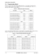
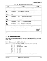
The AIPI is responsible for telling the IP bus peripherals if the access is in supervisor or user mode. The
AIPI may block user mode accesses to certain IP bus peripherals or it may allow the individual IP bus
peripherals to determine if user mode accesses are allowed. Please see Section 7.2, “Programming Model,”
for more information.
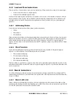
The AIPI supports multi-cycle accesses to IP bus peripherals when the R-AHB master requests data
transfers that are larger than the targeted IP bus peripheral’s data bus width. Table 7-1 through Table 7-4
provides more information on both single-cycle and multi-cycle accesses. For data access that are larger
than the target IP bus peripheral, the AIPI will duplicated the data across all the byte lanes on the AHB, i.e.
for a word read from 8 bit peripheral, the same data read will appear on byte lanes [31:24, [23:16], [15:8]
and [7:0]. Similarly for a byte write to the peripheral, the core will duplicate the same byte over the byte
lanes of the AHB for the write operation.
Figure 7-1. AIPI Interface
haddr[16:0]
HWDATA[31:0]
HWDATA[31:0]
AIPI_HRDATA[31:0]
HPROTL
HTRANSL
HWRITE
HSIZE[1:0]
HREADY_IN
AIPI_HRESP[1:0]
AIPI_HREADY_OUT
HCLK
HCLK
HSEL_AIPI
HRESET
BIGEND_IN
IPS_WDATA[31:0]
IPS_RDATA[15:1][31:
IPS_MODULE_EN[15:
IPS_ADDR1[11:1]
IPS_BYTE_7_0
IPS_BYTE_15_8
IPS_BYTE_23_16
IPS_BYTE_31_24
IPS_RWB
IPS_XFR_WAIT[15:1]
IPS_XFR_ERR[15:1]
IPS_SUPERVISOR_A
IPS_GATED_CLK_EN[1
AIPI
IP BUS SIG
N
ALS
Summary of Contents for DragonBall MC9328MX1
Page 68: ...1 12 MC9328MX1 Reference Manual MOTOROLA Introduction ...
Page 86: ...2 18 MC9328MX1 Reference Manual MOTOROLA Signal Descriptions and Pin Assignments ...
Page 116: ...3 30 MC9328MX1 Reference Manual MOTOROLA Memory Map ...
Page 126: ...4 10 MC9328MX1 Reference Manual MOTOROLA ARM920T Processor ...
Page 160: ...8 8 MC9328MX1 Reference Manual MOTOROLA System Control ...
Page 272: ...13 32 MC9328MX1 Reference Manual MOTOROLA DMA Controller ...
Page 281: ...Programming Model MOTOROLA Watchdog Timer Module 14 9 ...
Page 282: ...14 10 MC9328MX1 Reference Manual MOTOROLA Watchdog Timer Module ...
Page 300: ...15 18 MC9328MX1 Reference Manual MOTOROLA Analog Signal Processor ASP ...
Page 438: ...18 16 MC9328MX1 Reference Manual MOTOROLA Serial Peripheral Interface Modules SPI 1 and SPI 2 ...
Page 478: ...19 40 MC9328MX1 Reference Manual MOTOROLA LCD Controller ...
Page 574: ...21 32 MC9328MX1 Reference Manual MOTOROLA Memory Stick Host Controller MSHC Module ...
Page 598: ...23 16 MC9328MX1 Reference Manual MOTOROLA Real Time Clock RTC ...
Page 670: ...24 72 MC9328MX1 Reference Manual MOTOROLA SDRAM Memory Controller ...
Page 726: ...25 56 MC9328MX1 Reference Manual MOTOROLA SmartCard Interface Module SIM ...
Page 736: ...26 10 MC9328MX1 Reference Manual MOTOROLA General Purpose Timers ...
Page 854: ...29 18 MC9328MX1 Reference Manual MOTOROLA I2C Module ...
Page 900: ...30 46 MC9328MX1 Reference Manual MOTOROLA Synchronous Serial Interface SSI ...
Page 942: ...32 26 MC9328MX1 Reference Manual MOTOROLA GPIO Module and I O Multiplexer IOMUX ...


