25-2
MC9328MX1 Reference Manual
MOTOROLA
SmartCard Interface Module (SIM)
25.2.1 SIM Clock Generator
The SIM generates the clocks used within the SIM, and the clock signal provided to the SmartCard. The
clock generator has the following features:
•
Reference clock divide by 2, 4, 8, 12, 16, 20, 25, or 30 SmartCard clock generation (50% duty cycle
except for divide by 25 which has 48% duty cycle)
•
Legacy transmitter clock generation (/16, /32, /64, /128, /256, /372)
•
Legacy receiver clock generation (16X transmitter clock; 12X in /372 mode)
•
Programmable divisor for transmitter clock generation
The SIM clock does not generate any interrupts.
25.2.2 SIM Transmitter
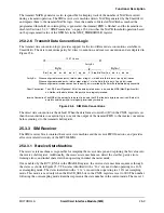
The transmitter portion of the SIM contains the transmit state machine, transmit shift register, and transmit
FIFO. The transmitter portion of the SIM has a 16 byte transmit FIFO and automatic NACK generation on
parity and overrun errors. Hardware data format support (inverse convention or direct convention) is
provided. The module also produces retransmission of data upon SmartCard NACK request with
configurable maximum threshold of retransmission and programmable guard time between transmitted
bytes. The SIM generates the six interrupts as shown in Table 25-1.
25.2.3 SIM Receiver
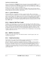
The receiver section of the SIM contains the receive state machine, receive FIFO, and control logic. The
receiver has a 32 (word) deep receive FIFO. The SIM receiver also provides decoding of initial character
mode for setting data format and hardware data format support (inverse convention or direct convention).
NACK detection, eleven elementary time unit (ETU) character support, and a character wait time counter
are provided. The SIM receiver generates the three interrupts shown in Table 25-2.
Table 25-1. SIM Transmitter Interrupt Summary
Flag
Flag Register
1
1.
See Section 25.6.5, “Transmit Status Register,” for more information.
Mask
Mask Register
2
2.
See Section 25.6.7, “Interrupt Mask Register,” for more information.
Description
TC
XMT_STATUS
TCIM
INT_MASK
Transmit complete
ETC
XMT_STATUS
ETCIM
INT_MASK
Early transmit complete
TFE
XMT_STATUS
TFEIM
INT_MASK
Transmit FIFO empty
XTE
XMT_STATUS
XTM
INT_MASK
Transmit threshold error
TFO
XMT_STATUS
TFOM
INT_MASK
Transmit FIFO overfill error
TDTF
XMT_STATUS
TDTFM
INT_MASK
Transmit data threshold
Summary of Contents for DragonBall MC9328MX1
Page 68: ...1 12 MC9328MX1 Reference Manual MOTOROLA Introduction ...
Page 86: ...2 18 MC9328MX1 Reference Manual MOTOROLA Signal Descriptions and Pin Assignments ...
Page 116: ...3 30 MC9328MX1 Reference Manual MOTOROLA Memory Map ...
Page 126: ...4 10 MC9328MX1 Reference Manual MOTOROLA ARM920T Processor ...
Page 160: ...8 8 MC9328MX1 Reference Manual MOTOROLA System Control ...
Page 272: ...13 32 MC9328MX1 Reference Manual MOTOROLA DMA Controller ...
Page 281: ...Programming Model MOTOROLA Watchdog Timer Module 14 9 ...
Page 282: ...14 10 MC9328MX1 Reference Manual MOTOROLA Watchdog Timer Module ...
Page 300: ...15 18 MC9328MX1 Reference Manual MOTOROLA Analog Signal Processor ASP ...
Page 438: ...18 16 MC9328MX1 Reference Manual MOTOROLA Serial Peripheral Interface Modules SPI 1 and SPI 2 ...
Page 478: ...19 40 MC9328MX1 Reference Manual MOTOROLA LCD Controller ...
Page 574: ...21 32 MC9328MX1 Reference Manual MOTOROLA Memory Stick Host Controller MSHC Module ...
Page 598: ...23 16 MC9328MX1 Reference Manual MOTOROLA Real Time Clock RTC ...
Page 670: ...24 72 MC9328MX1 Reference Manual MOTOROLA SDRAM Memory Controller ...
Page 726: ...25 56 MC9328MX1 Reference Manual MOTOROLA SmartCard Interface Module SIM ...
Page 736: ...26 10 MC9328MX1 Reference Manual MOTOROLA General Purpose Timers ...
Page 854: ...29 18 MC9328MX1 Reference Manual MOTOROLA I2C Module ...
Page 900: ...30 46 MC9328MX1 Reference Manual MOTOROLA Synchronous Serial Interface SSI ...
Page 942: ...32 26 MC9328MX1 Reference Manual MOTOROLA GPIO Module and I O Multiplexer IOMUX ...

