64
115895B System Installation Manual
MODBUS SERIAL COMMUNICATION OPTION SECTION
Reading a log is done with MODBUS Function Code 0x14 (Read File
Record). See the description of the Read File Record function code in the
MODBUS Application Protocol Specification document from
http://www.modbus.org/specs.php
•
Sub Request Reference Type must be
0x06
•
Sub Request File Number must be
0x0001
,
0x0002
or
0x0003
.
o
File Number 0x0001 is used to access the Alarm Log file
o
File Number 0x0002 is used to access the Event Log file
o
File Number 0x0003 is used to access the Test Log file
o
Note: File number 0x0004 can be used to read out the Custom
User ID string (see
•
Sub Request Record Number must be between 0x0000 and the file size
(retrieved through the respective register; 112, 113 or 114).
•
The Sub Request Record Data is returned by the MODBUS
Communication Option Board in 16-bit
‘byte pairs’. The MODBUS
Communication Option Board will always populate the first (most
significant) byte of a pair with 0x00, and will put a byte from the respective
file in the second (least significant) byte of the pair.
•
All bytes from the files are going to be printable ASCII characters, or tabs
(ASCII 0x09), or DOS style line endings (ASCII 0x0D, and ASCII 0x0A).
See the sections below to understand how to parse the data in the files.
Example
In this example, we will retrieve the contents of the Alarm Log file.
•
Step 1:
The first step is to determine the current size of the Alarm Log file.
We do this using the Read Holding Registers (0x03) function, on register
0x70 (112 - the Alarm Log File Size register). Let
’s assume we transmit
the following PDU
…
03 00 70 00 01
…
and receive the following PDU in response from the MODBUS
Communication Option Board:
03 02 00 37
The response says that the Alarm Log file is currently 0x37 (55) bytes
long.
•
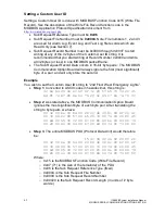
Step 2
: Now we have to use function code 0x14 (Read File Record) to
retrieve the Alarm Log file. For the sake of this example, let
’s read the
Alarm Log file in two transactions; a 32-byte read, followed by a 55
– 32 =
23 byte read. Here are the request PDUs and response PDUs:
Request PDU 1
14 07 06 00 01 00 00 00 20
Where:
o
0x14 (20) is the Read File Record function code
o
0x07 is the remaining length of the PDU in bytes
o
0x06 is the Reference Type (fixed)
Summary of Contents for Illuminator Supernova Series
Page 16: ...15 115895B System Installation Manual Figure 5 2 AC Connections for 6 25 k W 7 5 kW systems ...
Page 17: ...16 115895B System Installation Manual Figure 5 3 AC Connections for 10 kW 16 7 kW systems ...
Page 30: ...115895B System Installation Manual PART II OPTIONS MANUALS Section continues on next page ...
Page 95: ...94 115895B System Installation Manual SERIAL TO ETHERNET ADAPTER OPTION SECTION ...
Page 96: ...95 115895B System Installation Manual SERIAL TO ETHERNET ADAPTER OPTION SECTION ...
Page 114: ...113 115895B System Installation Manual DRAWINGS SECTION ...
Page 115: ...114 115895B System Installation Manual DRAWINGS SECTION ...
Page 116: ...115 115895B System Installation Manual DRAWINGS SECTION ...
Page 117: ...116 115895B System Installation Manual DRAWINGS SECTION ...
Page 118: ...117 115895B System Installation Manual DRAWINGS SECTION ...
Page 119: ...118 115895B System Installation Manual DRAWINGS SECTION ...
Page 120: ...119 115895B System Installation Manual DRAWINGS SECTION ...
Page 121: ...120 115895B System Installation Manual DRAWINGS SECTION ...
Page 122: ...121 115895B System Installation Manual DRAWINGS SECTION ...
Page 123: ...122 115895B System Installation Manual DRAWINGS SECTION ...
Page 124: ...123 115895B System Installation Manual DRAWINGS SECTION ...
Page 125: ...124 115895B System Installation Manual DRAWINGS SECTION ...
Page 126: ...125 115895B System Installation Manual DRAWINGS SECTION ...
Page 127: ...126 115895B System Installation Manual DRAWINGS SECTION ...
Page 128: ...127 115895B System Installation Manual DRAWINGS SECTION ...
Page 129: ...128 115895B System Installation Manual DRAWINGS SECTION ...
Page 130: ...129 115895B System Installation Manual DRAWINGS SECTION ...
Page 131: ...130 115895B System Installation Manual Notes ...


