Chapter 16: Controlling Access to the ER-1000
TR0190 Rev. B1
101
CLI
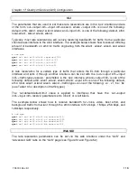
The firewall is enabled by selecting the ‘firewall’ interface and setting the ‘node.enable’
parameter.
>
use firewall
firewall>
set node.enable=yes
Lists of allowed source and destination ports for inbound TCP and UDP traffic can be
specified. These lists can be set with the following parameters in the ‘firewall’ interface:
•
node.tcp.allow.dest
•
node.tcp.allow.source
•
node.udp.allow.dest
•
node.udp.allow.source
The list of allowed ports must be a space-delimited string enclosed by quotes. The example
below shows how to set the TCP source ports parameters.
>
use firewall
firewall>
set node.tcp.allow.dest=”22 23 80 5280”
Web GUI
It is not possible to configure the state of the firewall and the open firewall ports via the web
interface. It is enabled by default.
16.2 Gateway Firewall
The gateway firewall blocks connections originating outside the EL-500 and its client address
spaces from entering the device, protecting VAP client devices from unwanted traffic. The
gateway firewall will permit return traffic for connections that originate from devices in the VAP
client subnets.
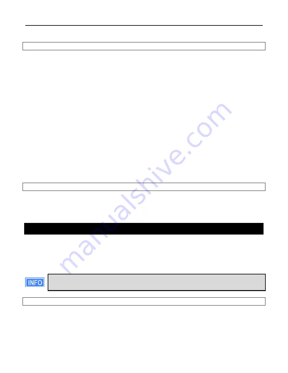
If you have enabled NAT (see section 15.1.2), you will have an implicit firewall that
limits the type of inbound connections that are possible.
CLI
The state of the gateway firewall is controlled with the ‘gateway’ parameter in the ‘firewall’
interface. Enable the gateway firewall with
>
use firewall
Summary of Contents for EL-500
Page 20: ...Chapter 3 Using the Web Interface TR0190 Rev B1 20 Figure 8 Rebooting the EL 500...
Page 68: ...Chapter 11 Ethernet Interface Configuration TR0190 Rev B1 68 Figure 38 Wired DHCP settings...
Page 108: ...Chapter 16 Controlling Access to the ER 1000 TR0190 Rev B1 108 Figure 50 VAP ACL configuration...

