Chapter 10: Client Addressing Schemes
TR0190 Rev. B1
61
Interface
Interface address
Broadcast address
Client device address range
wlan1
subnet.1
subnet.127
subnet.2-126
wlan2
subnet.129
subnet.159
subnet.130-158
wlan3
subnet.161
subnet.191
subnet.162-190
wlan4
subnet.193
subnet.223
subnet.194-222
subnet = <LAN prefix first octet>.<LAN prefix second octet >.<node ID>
Table 7. Default subnet segmentation between interfaces
10.1.1
LAN Prefix
The LAN prefix parameter sets the first two octets of the client access interface IP address
when using the implicit addressing scheme. The suggested values for the LAN prefix are 10.x
and 192.168.
The LAN prefix parameter only has an effect on an EL-500 using the explicit addressing
scheme when explicit addresses have not been defined for the client access interfaces. See
section 10.2 for more information on use of the LAN prefix when using the explicit addressing
scheme.
CLI
The first octet of the LAN prefix is set with the ‘id.lanprefix’ parameter in the ‘sys’ interface as
shown in the example below.
>
use sys
sys>
id.lanprefix=10
The second octet is set with the ‘id.mesh’ parameter in the ‘sys’ interface as shown below.
>
use sys
sys>
id.mesh=12
Web GUI
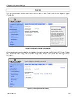
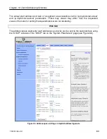
The LAN prefix can be set via the web interface using the “System” tab on the “System
Parameters” page (see Figure 34).
10.1.2
Client Address Space Segmentation in Implicit Addressing Mode
As mentioned above, the client access interfaces must share a class C address space when
the EL-500 is using the implicit addressing scheme. The start address of each address
segment and its size can be set. The following restrictions are placed on the address segment
configuration:
Summary of Contents for EL-500
Page 20: ...Chapter 3 Using the Web Interface TR0190 Rev B1 20 Figure 8 Rebooting the EL 500...
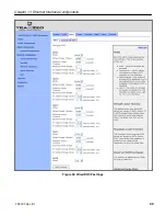
Page 68: ...Chapter 11 Ethernet Interface Configuration TR0190 Rev B1 68 Figure 38 Wired DHCP settings...
Page 108: ...Chapter 16 Controlling Access to the ER 1000 TR0190 Rev B1 108 Figure 50 VAP ACL configuration...


