Chapter 11: Ethernet Interface Configuration
TR0190 Rev. B1
69
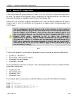
11.2 Manual IP Configuration
If the Ethernet DHCP mode parameter is set to ‘none’, the manually configured IP address will
be used. The default IP configuration that is assigned to the interface based on the LAN prefix
and node ID settings is available through the CLI and the web GUI.
Note that for the manually configured IP address to be used, the Ethernet DHCP mode setting
must be set to ‘none’ if the EL-500 is connected to a network which provides access to a
DHCP server.
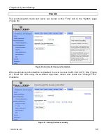
The IP configuration settings shown in the ‘eth0’ interface in the CLI and on
the “Wired Interface” page of the web interface do not necessarily reflect the
current settings of the interface. They are the requested settings and do not
take into account whether the interface has been configured via DHCP. If the
Ethernet DHCP mode parameter is set to ‘client’, the ‘ip.address’,
ip.broadcast’, ‘ip.gateway’, and ‘ip.netmask’ parameters will respond to a ‘get’
command with ‘<dhcp>’ to indicate that the parameters will be assigned by a
DHCP server instead of any values assigned via the CLI. Use the ‘ifconfig eth0’
command in the CLI or access the “Status” page in the web interface to get
current interface settings.
CLI
The Ethernet default IP configuration is available through the following read-only parameters:
•
ip.address – IP address
•
ip.broadcast – IP broadcast address
•
ip.gateway – default gateway
•
ip.netmask – netmask
These parameters cannot be set though. These default parameters can be overridden with the
parameters listed below.
•
ip.address_force
•
ip.broadcast_force
•
ip.gateway_force
•
ip.netmask_force
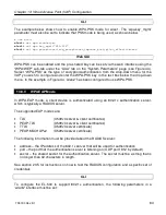
The example below, shows how a custom IP address can be set for the Ethernet interface
>
use eth0
eth0>
set dhcp=none
eth0>
set ip.address_force=192.168.1.2
eth0>
set ip.broadcast_force=192.168.1.255
eth0>
set ip.gateway_force=192.168.1.1
Summary of Contents for EL-500
Page 20: ...Chapter 3 Using the Web Interface TR0190 Rev B1 20 Figure 8 Rebooting the EL 500...
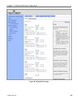
Page 68: ...Chapter 11 Ethernet Interface Configuration TR0190 Rev B1 68 Figure 38 Wired DHCP settings...
Page 108: ...Chapter 16 Controlling Access to the ER 1000 TR0190 Rev B1 108 Figure 50 VAP ACL configuration...

