background image

Chapter 13: Virtual Access Point (VAP)

 Configuration


 TR0190 Rev. B1 


86 

CLI 

The example below shows how to set the access point radio’s maximum transmit power using 
the CLI. The Tx power is specified in dBm, with a granularity of 0.5 dBm.  
 

>

 use wlan1 

wlan1>

 set txpower=20 


Web GUI 

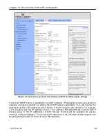
The  VAPs’  maximum  transmit  power  can  be  set  via  the  web  interface  using  the  appropriate 
“wlan

N

” tab on the “Wireless Interfaces” page (see Figure 41). The “+” and “-“ buttons can be 

used to increase or decrease the power setting in 0.5 dBm steps. 

13.10  Radio Rate 

The VAPs can be set to communicate at a specific rate or to automatically select the best rate 
available. For most applications, choosing automatic rate selection will be the best choice. 
 

CLI 

It  is  not  currently  possible  to  set  this  through  the  CLI.  Please  use  the  web  GUI  to  set  this 
parameter.  
 

Web GUI 

The VAPs’ communication rate can be set via the web interface using the appropriate “wlan

N

” 

tab  on  the  “Wireless  Interfaces”  page  (see  Figure  41).  To  limit  communication  to  a  specific 
rate,  use  the  drop-down  menu  to  select  the  appropriate  rate  and  verify  that  the  “Auto” 
checkbox is not selected. To set the device to automatically select the most appropriate rate, 
click on the “Auto” checkbox to select it. 

13.11  Preamble Length 

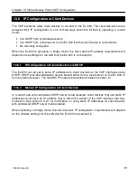
The VAPs can be configured to use short preambles when there are no client devices present 
that  only  support  long  preambles.  Alternatively,  the  device  can  be  forced  to  always  use  long 
preambles.  Using  short  preambles  reduces  communication  overhead,  but  may  not  be 
supported by older 802.11 client devices. 
 

The  preamble  length  setting  is  uniform  across  all  VAPs.  Changing  it  for  one 
will automatically change it for all others as well. 


Summary of Contents for EL-500

Page 1: ...Rev B1 EL 500 Access Point User s Guide Rev B1 Communicate Without Boundaries Tranzeo Wireless Technologies Inc 19473 Fraser Way Pitt Meadows BC Canada V3Y 2V4 www tranzeo com technical support email...

Page 2: ...are trademarks of Tranzeo Wireless Technologies Inc All rights reserved All other company brand and product names are referenced for identification purposes only and may be trademarks that are the pr...

Page 3: ...radio or television reception which can be determined by turning the equipment off and on the user is encouraged to try to correct the interference by one or more of the following measures Reorient or...

Page 4: ...sing the Web Interface 16 3 1 Accessing the Web Interface 16 3 2 Navigating the Web Interface 18 3 3 Setting Parameters 18 3 4 Help Information 19 3 5 Rebooting 19 4 Using the Command Line Interface 2...

Page 5: ...7 Configuration Profile Management 41 7 1 Saving the Current Configuration 41 7 2 Load a Configuration Profile 42 7 3 Delete a Configuration Profile 42 7 4 Downloading a Configuration Profile from an...

Page 6: ...evices via DHCP 79 13 6 2 Manual IP Configuration of Client Devices 79 13 7 Client Devices 81 13 8 Encryption and Authentication 81 13 8 1 WEP Encryption 82 13 8 2 WPA Pre Shared Key Mode WPA PSK 83 1...

Page 7: ...117 18 2 Ethernet Interface Configuration 118 19 Integration with Enterprise Equipment 120 19 1 Configuring Splash Pages 120 19 1 1 Enabling Splash Pages 120 19 1 2 Configuring Splash URLs 122 19 1 3...

Page 8: ...hout the manual EL 500 will be used to collectively refer to this family of products Where the functionality of the variants differs the actual model number will be used 1 2 EL 500 Capabilities Based...

Page 9: ...inspection o Custom firewall rules Web GUI Tranzeo CLI SSH Remote upgrade Configuration management 1 3 EL 500 Interfaces The interfaces available on the EL 500 are Ethernet and a radio port Ethernet F...

Page 10: ...age between 9 28VDC and a minimum of 12W The pinout for the Ethernet interface on the EL 500 is provided in Table 3 The EL 500 is equipped with an auto sensing Ethernet port that allows both regular a...

Page 11: ...regulatory requirements in the area the EL 500 is used 1 4 Deployment Considerations The EL 500 s radio operates in either the 2 4 GHz or the 5 8 GHz ISM band depending on the model It is possible tha...

Page 12: ...Chapter 1 Working with the ER 1000 TR0190 Rev B1 12 Figure 2 802 11b g channel chart showing top bottom and center frequencies for each channel...

Page 13: ...N A Access to the device when operating in bridge mode Enabled in bridge mode 10 253 1 1 24 No Static Configuration Ethernet Configuring the device before a unique Ethernet IP address has been configu...

Page 14: ...mputer s IP address to be in the 169 254 253 253 16 subnet e g 169 254 253 1 and connect the computer s Ethernet cable to the PC port on the EL 500 s PoE injector ENSURE THAT THE DATA CONNECTION FROM...

Page 15: ...login is admin and the default password is default The login and password are the same for the web interface and the CLI Changing the password using one of the interfaces will change it for the other...

Page 16: ...escription of how to access an unconfigured EL 500 using its Ethernet interface When you enter this URL you will be prompted for a login and password The default login and password used for the web in...

Page 17: ...ter or bridge Bridge information if bridge mode is selected IP addresses netmasks and MAC addresses for each client access interface Status channel ESSID and encryption type for each virtual access po...

Page 18: ...d on the navigation bar 3 The third tier of navigation is the second row of tabs shown below the first row These tabs are not present on all pages and their labels vary based on the selections made on...

Page 19: ...age prompting the user to reboot 3 4 Help Information Help information is provided on most web GUI pages The help information is shown on the right hand side of the page The help information can be hi...

Page 20: ...Chapter 3 Using the Web Interface TR0190 Rev B1 20 Figure 8 Rebooting the EL 500...

Page 21: ...equired for devices that have not previously been configured Windows XP does not include an SSH client application You will need to install a 3rd party client such as SecureCRT from Van Dyke software...

Page 22: ...ion displays version information for the installed firmware system system settings The currently selected interface is shown as part of the command prompt For example when the wlan1 interface is selec...

Page 23: ...xecuted commands When you find the command you wish to execute you can either edit it or press Return to execute it 4 5 CLI Commands The usage of all CLI commands is explained in the following subsect...

Page 24: ...en a command is supplied as the argument a help message for that particular command is displayed When a parameter in the current interface is specified as the argument help information for it is displ...

Page 25: ...e where parameter is the parameter being set and value is the value it is being set to Description Sets a configuration parameter Note that is only possible to set the parameters for the currently sel...

Page 26: ...iple values to be fetched with a single command Example With the eth0 interface selected get ip address will return the Ethernet interface s IP address while get ip will return all parameters that beg...

Page 27: ...read only ip broadcast_force override ip broadcast or blank ip gateway gateway read only ip gateway_force override ip gateway or blank ip implicit size actual actual size of address range ip implicit...

Page 28: ...encap Ethernet HWaddr 00 15 6D 52 01 FD inet addr 10 2 10 1 Bcast 172 29 255 255 Mask 255 255 0 0 UP BROADCAST RUNNING MULTICAST MTU 1500 Metric 1 RX packets 0 errors 0 dropped 0 overruns 0 frame 0 TX...

Page 29: ...story command Syntax history Description Shows the command history since the EL 500 was last rebooted Example After switching to the wlan1 interface inspecting the ESSID setting and then changing it h...

Page 30: ...mand history with a number preceding each entry in the command history Use this number as an argument to the command to execute that command from the history When a string is provided as an argument t...

Page 31: ...e Interface TR0190 Rev B1 31 4 5 15 exit command Syntax exit Description Terminates the current CLI session and logs out the user 4 5 16 quit command Syntax quit Description Terminates the current CLI...

Page 32: ...ee section 9 1 2 Set the node ID The node ID affects the client access interface IP address spaces when the using implicit addressing scheme See section 9 2 3 Set the DNS servers Specify DNS servers t...

Page 33: ...Chapter 5 Initial Configuration of an ER 1000 TR0190 Rev B1 33 Figure 9 Initial configuration web page...

Page 34: ...ccessible through the CLI 6 1 Configuration Overview Page The main status page which is displayed when clicking on Status in the navigation bar and when logging in is the Config Overview page Figure 1...

Page 35: ...r the interface are displayed showing received and transmitted data in terms of bytes and packets On the wlan sub tabs the client devices connected to the virtual APs are displayed The following infor...

Page 36: ...interface and does not break down data transferred on a per device basis Figure 12 Wired interface status information 6 3 Bridging The Bridging tab is only present when the EL 500 is in bridge mode T...

Page 37: ...apter 6 Status Information TR0190 Rev B1 37 Figure 13 Bridging status information 6 4 Routing Table The routing table used by the device can be displayed by selecting the Routing tab on the Status pag...

Page 38: ...Chapter 6 Status Information TR0190 Rev B1 38 Figure 14 Routing table 6 5 ARP Table The device s ARP table can be displayed by selecting the ARP tab on the Status page Figure 15 ARP table...

Page 39: ...time maintained by the EL 500 and may not be consistent with that shown in the upper left corner of the webpage as this is the time maintained by the computer running the web browser 6 7 DHCP Event Lo...

Page 40: ...17 DHCP event log The time reported in the DHCP Log corresponds to the time maintained by the EL 500and may not be consistent with that shown in the upper left corner of the webpage as this is the tim...

Page 41: ...on the EL 500 to a computer Uploading a configuration profile from a computer to the EL 500 Deleting a configuration profile stored on the EL 500 Currently configuration profile management is only sup...

Page 42: ...xisting Profiles box and then click on Load Profile It is necessary to reboot the EL 500 for the loaded profile settings to take effect A number of default configuration profiles are available on the...

Page 43: ...ile can be download from an EL 500 using the Download from node tab on the Profile Management page The existing configuration profiles are listed on this page Click on the one that is to be downloaded...

Page 44: ...the Upload to node tab on the Profile Management page Use the Browse button to select a profile file on your host computer for upload to the EL 500 Alternatively enter the file name by hand in the tex...

Page 45: ...d by a local DHCP server on the EL 500 or can be forwarded to a centralized server Splash pages Not available Available Firewall Custom firewall rules cannot be added Custom firewall rules can be adde...

Page 46: ...he sys interface Valid values are aponly for routed mode and l2bridge for bridge mode For example set the operating mode to routed mode with use sys sys set scheme aponly Web GUI The operating mode ca...

Page 47: ...ion 2 4 for instructions on resetting the admin password if it has been lost CLI The password for the admin user can be set using the password admin parameter in the sys interface The password will no...

Page 48: ...access interfaces when it uses implicit addressing in routed mode If multiple EL 500s are connected to the same LAN it is recommended that they be assigned different node IDs unless they have the NAT...

Page 49: ...any manually set DNS server setting When operating in bridge mode the DNS settings are only used locally by the EL 500 and are not provided to any other devices on the network CLI The DNS server s use...

Page 50: ...cified using the dnsproxy hosts parameter in the sys interface If multiple hostname IP address entries are specified they must be separated by semi colons as shown in the example below DNS proxy must...

Page 51: ...dary NetBIOS server can be set via the web interface using the DNS tab on the System Parameters page see Figure 26 9 6 SNMP The EL 500 supports SNMP The read only and read write passwords and the port...

Page 52: ...see Figure 28 Figure 28 SNMP configuration 9 7 Location Two types of device location information can be stored Latitude longitude altitude Postal address or description a device s location Note that...

Page 53: ...ue as follows use sys sys set location gps latitude 34 01 A description of the EL 500 s location can be stored in the location postal field in the sys interface For example you can set the location va...

Page 54: ...s organization state state name sys organization country two letter country abbreviation Web GUI The certificate information can be set via the web interface using the Location tab on the System Param...

Page 55: ...n the Time tab on the System page Figure 30 Figure 30 Automatic time synchronization When automatic synchronization is disabled the user can set the EL 500 s UTC time Figure 31 Enter the time using th...

Page 56: ...tual AP wlan1 To use the console enter one or more key value pairs in the large text box on the page either separating each pair with a space or placing each pair on its own line Click on the Submit C...

Page 57: ...ther a device can be configured from OnRamp In OnRamp the Prog column displays the programming capability from OnRamp A Y in this column indicates that OnRamp can configure the device an N indicates t...

Page 58: ...ined inactive for a certain length of time The time in seconds that a shell must remain inactive before a user is automatically logged out is set with the shell timeout parameter in the sys interface...

Page 59: ...g scheme Explicit addressing scheme Client access interface addresses Derived from node ID and LAN prefix settings Client access interface addresses cannot be directly set Can be set to arbitrary valu...

Page 60: ...e node ID and the LAN prefix as shown in Figure 35 Figure 35 Subnet address structure If the EL 500 is operating in centralized DHCP server mode the addresses used for the implicit addressing scheme h...

Page 61: ...when explicit addresses have not been defined for the client access interfaces See section 10 2 for more information on use of the LAN prefix when using the explicit addressing scheme CLI The first o...

Page 62: ...No No 193 Yes Yes No No 225 Yes No No No Table 8 Allowed address segment start address and size combinations Each of the enabled interfaces address segments should be configured to avoid overlap with...

Page 63: ...actual parameters These may values may differ from the requested values if the rules for setting these parameters were not abided by Web GUI The address space segments start addresses and sizes can be...

Page 64: ...at you want client devices to be able to connect to Do not specify a gateway IP address for any of the client access interfaces when operating using the explicit addressing scheme This field should be...

Page 65: ...r 10 Client Addressing Schemes TR0190 Rev B1 65 See section 13 3 for instructions on how to set the IP addresses for the wired and wireless client access interfaces when using the explicit addressing...

Page 66: ...ect the EL 500 to a LAN It is also used for initial configuration of the device The Ethernet interface IP address can either be acquired from a DHCP server on the LAN or be set manually Figure 37 Wire...

Page 67: ...he eth0 interface to client as shown in the example below use eth0 eth0 set dhcp role client To disable Ethernet DHCP client mode set the DHCP mode parameter to none as shown below use eth0 eth0 set d...

Page 68: ...Chapter 11 Ethernet Interface Configuration TR0190 Rev B1 68 Figure 38 Wired DHCP settings...

Page 69: ...red via DHCP If the Ethernet DHCP mode parameter is set to client the ip address ip broadcast ip gateway and ip netmask parameters will respond to a get command with dhcp to indicate that the paramete...

Page 70: ...70 eth0 set ip netmask_force 255 255 255 0 Web GUI The Ethernet IP address gateway netmask and broadcast address parameters can be set via the web interface using the Wired Interface page see Figure...

Page 71: ...For these settings to be used the bridge interface DHCP mode must be disabled using the dhcp role parameter in the br0 interface as shown in the example below The example below shows how to manually s...

Page 72: ...e with DHCP client mode disabled The DHCP mode for the bridge interface is set on the DHCP tab on the System page When bridge mode is selected the only setting available on this page is the bridge DHC...

Page 73: ...elay will be automatically set to 15 to avoid DHCP requests timing out The EL 500 supports the Spanning Tree Protocol STP which is used to ensure a loop free topology for any bridged LAN STP support c...

Page 74: ...ommon radio but with a few exceptions noted in this chapter can be configured independently The availability of the four VAPs provides more flexibility in configuration and catering to different user...

Page 75: ...the following commands use wlan1 wlan1 set enable no Web GUI Each VAP can be enabled or disabled by setting the State parameter via the web interface using the appropriate wlanN tab on the Wireless I...

Page 76: ...d lanprefix parameters in the sys interface and the ip implicit start requested parameter in the appropriate wlanN interface When an EL 500 is using the explicit addressing scheme the IP address netma...

Page 77: ...nnels 1 6 and 11 are non overlapping The EL 500HA has an 802 11a radio that can be set to operate in the channels listed in Table 10 Channel Center Frequency GHz 149 5 745 153 5 765 157 5 785 161 5 80...

Page 78: ...ces dashes and underscores _ The ESSID setting is case sensitive It is possible to hide a VAP ESSID by restricting it from broadcasting advertisements for that ESSID Whether it is appropriate for a VA...

Page 79: ...n of Clients Devices via DHCP The EL 500 can be set to serve IP addresses to client devices on the VAP interfaces using DHCP DHCP provided addresses can be served either from a local server on the EL...

Page 80: ...setting the DHCP reserve parameter This will reserve the specified number of IP addresses at the bottom of the IP range for the interface For example if the interface has the IP address 10 2 4 1 the...

Page 81: ...s information about attached client devices and total throughput through the VAP The signal strength of each client device its MAC address its IP address and the time since data was last received from...

Page 82: ...n The VAPs can be protected with a WEP based encryption key to prevent unauthorized users from intercepting or spoofing traffic CLI To enable WEP based encryption set the key parameter in the wlanN in...

Page 83: ...ng the WPA WEP sub tab under the AAA tab on the System Parameters page see Figure 44 Select WEP as the type of encryption from the drop down menu for the VAP you wish to configure and set the WEP key...

Page 84: ...wlan2 has been configured to use WPA PSK 13 8 3 WPA EAP Mode In WPA EAP mode a client device is authenticated using an 802 1x authentication server which is typically a RADIUS server The supported EA...

Page 85: ...r IP address port and secret in the text boxes below the drop down menu In the example in Figure 44 wlan3 has been configured to use WPA EAP 13 9 Transmit Power Cap The maximum transmit power cap of t...

Page 86: ...sible to set this through the CLI Please use the web GUI to set this parameter Web GUI The VAPs communication rate can be set via the web interface using the appropriate wlanN tab on the Wireless Inte...

Page 87: ...The VAPs beacon intervals are configurable The beacon interval must fall in the range from 20 to 500 ms The beacon interval is set to 100 ms by default CLI The example below shows how to set the beac...

Page 88: ...in either kilometers or miles The units parameter in the sys interface determines whether the distance units are to be entered in kilometers or miles Set units to metric for kilometers and to imperia...

Page 89: ...ing to but it will not provide any local DHCP functionality for client devices when operating in this mode Centralized DHCP server mode does not need to be configured in bridge mode since the relaying...

Page 90: ...own below Start address LAN prefix octet 1 LAN prefix octet 2 Node ID wlan1 IP address range start address 1 wlan1 DHCP reserve CLI The DHCP mode parameters in the wlanN interfaces control DHCP behavi...

Page 91: ...0 Rev B1 91 The DHCP reserve setting for all VAPs and the wired interface can be set via the web interface using the DHCP sub tab under the DHCP tab on the System Parameters page see Figure 45 Figure...

Page 92: ...ous It is recommended that a contiguous range of IP addresses at either the beginning or the end of the CAS be set aside one for each VAPs on the EL 500 The Client Address Space CAS is not equivalent...

Page 93: ...This will be supplied to DHCP client devices as their gateway This IP address can be the same as for the DHCP server but need not be Each client access interface on the EL 500 that is to support centr...

Page 94: ...et with the dhcp relay dhcp_subnet parameter in the sys interface This value should be a class A B or C subnet specified using CIDR notation as shown in the example below use sys sys set dhcp relay dh...

Page 95: ...ust be available in order to configure the server 1 The local interface to the DHCP server over which the DHCP related messages from the EL 500 arrive 2 The parameter s that define the address lease t...

Page 96: ...no routers option is needed If a global routers option is defined the EL 500 will automatically change it to an appropriate value in DHCP responses to client devices based on the centralized DHCP set...

Page 97: ...d need to forward to the EL 500 is 10 12 14 0 255 255 255 0 If the explicit addressing scheme is used all the individual client access interface subnets must be forwarded to the EL 500 s Ethernet IP a...

Page 98: ...e EL 500 is connected to The EL 500 and its client devices are able to communicate with devices connected to the external network However devices on the external network cannot initiate communication...

Page 99: ...can be set via the web interface on the Wired Interface page Figure 47 Figure 47 NAT and VPN settings 15 2 Bridge Mode In bridge mode the EL 500 can be connected to a LAN with minimal configuration Se...

Page 100: ...revents client devices attached to an EL 500 and devices on the LAN which the EL 500 is attached to from connecting to it The default firewall rules only affect packets destined for the EL 500 and hav...

Page 101: ...use firewall firewall set node tcp allow dest 22 23 80 5280 Web GUI It is not possible to configure the state of the firewall and the open firewall ports via the web interface It is enabled by default...

Page 102: ...her client access interface on the EL 500 Client to client traffic can be controlled for interfaces wlan1 wlan2 wlan3 and wlan4 CLI The parameters that control client to client access are all in the f...

Page 103: ...ion related firewall settings Note that devices connected to different interfaces can only communicate with each other if client to client isolation is disabled for both interfaces Client to client is...

Page 104: ...e conntrack table_size parameter use firewall firewall set conntrack table_size 16384 Web GUI The connection tracking table size is set with the Conntrack Size field on the Connections sub tab on the...

Page 105: ...to set the state of TCP connection limiting The conntrack connlimit connections parameter is used to set the maximum number of connections allowed per client device use firewall firewall set conntrac...

Page 106: ...port 25 dport 25 j DROP Limiting Access Based on Client Access Interface Packets can be filtered based upon which interface they were received through For example wlan1 and wlan2 can be used to provi...

Page 107: ...appropriate wlanN sub tab under the ACL tab on the Security page as shown in Figure 50 Enter a MAC address and click on the Add MAC button to add the address to the ACL for that VAP Once an address ha...

Page 108: ...Chapter 16 Controlling Access to the ER 1000 TR0190 Rev B1 108 Figure 50 VAP ACL configuration...

Page 109: ...ting is not applied The default flow priority is configurable Traffic originating from an interface with a higher priority will take priority over traffic from all interfaces with a lower priority val...

Page 110: ...lower hardware priority Instead the medium access delay will be reduced as dictated by the IEEE 802 11e standard for the traffic with the elevated hardware priority Thus these two priority types provi...

Page 111: ...hwpri max 2 The example below shows how to configure the system such that all traffic from wlan2 with a Background or Best Effort priority will be increased to a Video priority Traffic with Video and...

Page 112: ...53 The Control Points can be split into three groups listed below in decreasing order of importance Interface output limit Interface output limit of traffic from a particular interface Interface outp...

Page 113: ...dalone input rate limiting Limiting the input rate of an interface on the EL 500 only makes sense in the context of the output for another interface s In most cases you are concerned with eth0 as the...

Page 114: ...ollowing default eth0 wlan1 wlan2 wlan3 wlan4 input intf is one of the following default eth0 local wlan1 wlan2 wlan3 wlan4 traffic type is one of the following vo vi be bk see Table 13 for descriptio...

Page 115: ...hich rate reservations can be made are shown in Figure 54 These points are similar to where rate limits can be placed except that rate reservations require both an input and output interface whereas r...

Page 116: ...hrough a particular interface and exits it through another interface can be set with the out output intf input intf traffic type reserve parameters in the qos interface where output intf is one of the...

Page 117: ...2 for more details The VLAN ID value for each client access interface is set with the VLAN ID parameter for each interface The VLAN ID must be in the range from 0 to 4095 Note that 0 and 4095 are rese...

Page 118: ...net interface VLAN support must be enabled for the Ethernet interface The Enable VLAN parameter for the wired interface controls the state of VLAN tagging If VLAN tagging is enabled on the Ethernet in...

Page 119: ...4095 Note that 0 and 4095 are reserved values and 1 is the default VLAN ID CLI The example below shows how to enable VLAN tagging on Ethernet interface using the vlan enable parameter in the eth0 inte...

Page 120: ...n the Internet until they have logged in The splash page can require the user to enter logon credentials or simply click a button to complete the login process To use splash pages a number of URLs for...

Page 121: ...set the parameter for the wlan1 interface such that a user will be required to login to access the network use sys sys set splash auth server enable wlan1 yes Web GUI Splash pages can be enabled on a...

Page 122: ...t a user is redirected to when a login error has occurred For example this page would be displayed if a valid authentication server could not be reached If this variable is left blank a default page t...

Page 123: ...gi The DNS proxy entry which will be different for each deployed EL 500 must be mapped to one of the EL 500 s IP addresses see section 9 4 for more information on how to set DNS proxy configuration Th...

Page 124: ...till contain a form definition similar to that on line 6 in Figure 59 The action value must be set to point to a proxied server name just as for the case where a user is required to provide login cred...

Page 125: ...ver parameters can be set on the Splash Pages sub tab under the AAA tab on the System Parameters page of the web interface see Figure 57 using the fields for Login Server Address Login Server Port and...

Page 126: ...esses that client devices can access without the client devices having to view a splash screen CLI The list of hosts that can be accessed without having to view a splash screen is set with the splash...

Page 127: ...addresses of client devices that are connected to it In layer 2 emulation mode an EL 500 will respond to ARP requests if it has a route to the target IP address contained in the ARP request The list o...

Page 128: ...The state of layer 2 emulation is set on the System tab of the System page see Figure 61 The console interface in the web GUI must be used to configure which address ranges the EL 500 responds to ARP...

Page 129: ...inging the device The results of the pings will appear on the bottom half of the page shortly after clicking on the button There may be a delay of a few seconds to display the ping results if the ping...

Page 130: ...raffic From Clients on wlan1 1 Set Interface to wlan1 2 Set Protocol to all 3 Set Packet Count to 20 4 Set Packet length to 500 5 Click on DHCP next to Common Protocols 6 Set Output to File 7 Click on...

Page 131: ...s been captured or click on Stop Capture to halt the capture 9 The captured data is accessible by clicking on the link at the bottom of the page under the heading Available tcpdump files The file name...

Page 132: ...a host name or IP address to use for filtering purposes All packets with this host as their source OR destination address will be captured Optional Port Sets a port to use for filtering purposes All...

Page 133: ...o test in the Username and Password fields 3 Click on the Test User button The results of the test will be displayed at the bottom of the page Three outcomes are possible The credentials were authenti...

Page 134: ...of diagnostic dumps available for download is displayed at the bottom of the page The diagnostic dumps can be downloaded by clicking on the filenames To delete one or more diagnostic dumps select the...

Page 135: ...rface The example below shows how to display the current firmware version use version version get release release ENROUTE1000_20070911_03_00_0215 Web GUI The firmware version is displayed at the top o...

Page 136: ...e below to upgrade the firmware on a device 1 Select the firmware version you want to upgrade to from the Firmware on Server box 2 Click on the button with the arrow to the right of the Firmware on Se...

Page 137: ...e of the EL 500 s client access interfaces e g a laptop Client address scheme The method used to assign address spaces to client address interfaces The two supported client address schemes are implici...

Page 138: ...lan4 ESSID Extended Service Set Identifier LAN Local Area Network NAT Network Address Translation PoE Power over Ethernet QoS Quality of Service RSSI Received signal strength indicator STP Spanning Tr...

Reviews: