Chapter 13: Virtual Access Point (VAP)
Configuration
TR0190 Rev. B1
85
•
wpa.enable
•
wpa.key_mgmt
•
wpa.auth.server.addr
•
wpa.auth.server.port
•
wpa.auth.server.shared_secret
The ‘wpa.key_mgmt’ parameter must be set to indicate that both PSK and EAP modes can be
supported, as shown in the example below.
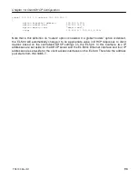
The example below shows how to enable WPA EAP mode.
>
use wlan1
wlan1>
set wpa.enable=yes
wlan1>
set wpa.key_mgmt=”WPA-PSK WPA-EAP”
wlan1>
set wpa.auth.server.addr=1.2.3.4
wlan1>
set wpa.auth.server.port=1812
wlan1>
set wpa.auth.shared_secret=enroute1000_radius_secret
Web GUI
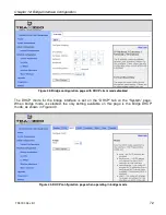
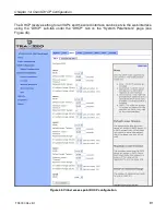
WPA-EAP can be enabled and the authentication server parameters can be set via the web
interface using the “WPA/WEP” sub-tab under the “AAA” tab on the “System Parameters” page
(see Figure 44). Select “WPA-EAP” as the type of encryption/authentication from the drop-
down menu for the VAP you wish to configure and set the authentication server IP address,
port, and secret in the text boxes below the drop-down menu. In the example in Figure 44,
‘wlan3’ has been configured to use WPA-EAP.
13.9 Transmit Power Cap
The maximum transmit power cap of the EL-500’s radio is configurable. Increased output
power will improve communication range, but will also extend the interference range of the
radios. By default, the power cap is set to 30 dBm so as not to limit the power of the AP.
If the transmit power is set to a value in excess of what can be supported by
the AP radio, the actual radio output power will be the highest power
supported by the AP radio.
When setting the output power for an VAP, consider the output power of the client
devices that will be communicating the VAP. If these devices have output power
levels that are far lower than that of the VAP, an asymmetric link may result. Such a
link exists when the received signal strength at client devices is sufficient for a
downlink to the client device be established, but the received signal level at the VAP
is not sufficient for an uplink from the client device to be established.
Summary of Contents for EL-500
Page 20: ...Chapter 3 Using the Web Interface TR0190 Rev B1 20 Figure 8 Rebooting the EL 500...
Page 68: ...Chapter 11 Ethernet Interface Configuration TR0190 Rev B1 68 Figure 38 Wired DHCP settings...
Page 108: ...Chapter 16 Controlling Access to the ER 1000 TR0190 Rev B1 108 Figure 50 VAP ACL configuration...


