Chapter 12: Bridge Interface Configuration
TR0190 Rev. B1
71
12 Bridge Interface Configuration
12.1 IP Configuration
The bridge interface has an IP address that can be set manually or acquired via DHCP. With
the exception of the fixed configuration IP address, this is the only active IP address on the
device when it is operating in bridge mode.
When not explicitly specifying an IP address or enabling DHCP client mode, the address for
the bridge interface will default to
<LAN prefix first octet>.<node ID>
.1.1.
CLI
The bridge IP settings are set with the ‘ip.address_force’, ‘ip.broadcast_force’,
‘ip.gateway_force’, and ‘ip.netmask_force’ parameters in the ‘br0’ interface. For these settings
to be used, the bridge interface DHCP mode must be disabled using the ‘dhcp.role’ parameter
in the ‘br0’ interface, as shown in the example below.
The example below, shows how to manually set an IP configuration for the bridge interface
>
use br0
br0>
set dhcp.role=none
br0>
set ip.address_force=10.5.1.27
br0>
set ip.broadcast_force=10.5.1.255
br0>
set ip.gateway_force=10.5.1.1
br0>
set ip.netmask_force=255.255.255.0
To set the DHCP mode to ‘client’ for the bridge interface, set the ‘dhcp.role’ parameter in the
‘br0’ interface to ‘client’ as shown below.
>
use br0
br0>
set dhcp.role=client
Web GUI
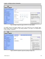
The IP address, gateway, netmask, and broadcast address parameters can be set on the “L2
Bridge” page when the DHCP mode for the bridge interface is set to ‘none’ (see Figure 13). A
link to the “L2 Bridge” page appears in the navigation bar when bridge mode is selected.
Summary of Contents for EL-500
Page 20: ...Chapter 3 Using the Web Interface TR0190 Rev B1 20 Figure 8 Rebooting the EL 500...
Page 68: ...Chapter 11 Ethernet Interface Configuration TR0190 Rev B1 68 Figure 38 Wired DHCP settings...
Page 108: ...Chapter 16 Controlling Access to the ER 1000 TR0190 Rev B1 108 Figure 50 VAP ACL configuration...


