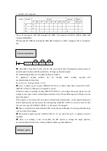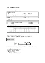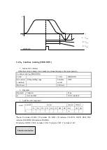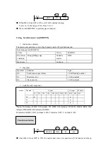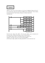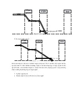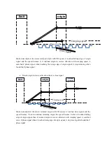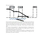
synchronous.
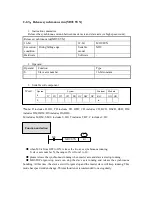
S0: synchronous motion speed times (floating number), which is master and slave axis speed.
S1: master axis no.N, the range of N is from 1 to 10.
S2: slave axis no.N, the range of N is from 1 to 10.
●
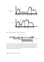
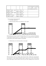
the synchronous speed mode depends on S0:
(1) S0 is negative value: slave axis keeps synchronous motion with master axis as reverse speed
times |S0|.
(2) S0 is 0, the slave axis bundles with master axis, but the slave axis speed is 0.
(3) S0 is positive value, slave axis keeps synchronous motion with master axis as speed times
S0.
●
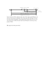
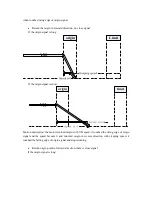
it can bundle when master and slave axis stop.
If the master axis stop, the slave axis is running, the slave axis cannot be bundled, the slave
axis will stop after the instruction end.
●
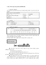
Modify the synchronous speed times through register (60*(N-1)), the times must be
floating number.
●
it can use with MOTO, MOTOA, MOTOS, MOSTOP to do synchronous motion.
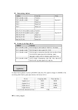
Table 1: parameters (N=1~10)
Address
Definition
Type
Unit
Mark
60*(N-1)
Synchronous
motion
speed
times
32-bit
floating
number
Motion axis speed/ target axis speed
60*(N-1)
Positioning
completion width
32-bit
integer
Pulse
number
Positioning complete threshold, if the
difference between setting value and
encoder feedback value is less than
this value, the running flag is OFF
60*(N-1)
synchronous
completion width
32-bit
integer
Pulse
numbers
/s
Synchronous complete threshold. The
speed difference between the two axes
is less than the threshold and position
difference
is
less
than
SFD_UC_NT_Complement,
then
SM_UC_NT_GetSync set ON
Table 2: state bit (N=1~10)
Address
Definition
Mark
20*(N-1)
Servo enable flag
ON: servo enable state
20*(N-1)
Running flag
ON: pulse is outputting
20*(N-1)
Direction flag
ON: positive direction
20*(N-1)
Synchronous flag
ON: keep synchronous state
20*(N-1)
Axis error flag
ON: error


