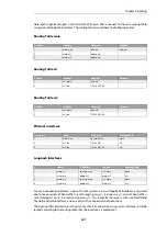
4.5. Virtual Routing
4.5.1. Overview
Virtual Routing
is a NetDefendOS feature that allows the creation of multiple, logically separated
virtual systems
within NetDefendOS, each with its own routing table. These systems can behave
as physically separated NetDefend Firewalls and almost everything that can be done with
separate firewalls can be done with them, including dynamic routing with OSPF. Virtual systems
are sometimes also referred to as
Virtual Routers
.
The NetDefendOS components involved in creating virtual routing are:
•
Separate routing tables for each virtual system.
•
Per-interface policy-based routing table membership to make interface IP addresses
reachable only via a particular routing table. This association can be made explicitly by
linking an interface with a specific routing table.
•
Pairs of loopback interfaces can be used for communication between virtual systems if
required (see also
Section 3.4.9, “Loopback Interfaces”
There are two ways of associating a specific routing table with a specific interface:
•
Using Routing Rules
Routing Rules
can be defined so that all traffic on a particular interface are subject to a
particular routing table.
•
Specifying a Routing Table for an Interface
It is possible to associate an interface directly with a specific routing table. This is known as
the interface's
routing table membership
. This option is part an interface's
virtual routing
options.
This is the preferred way of implementing a virtual router. The interface might be physical or
it could be a virtual LAN (VLAN).
To ensure that a routing table does not use any other tables in the route lookup process, the
Ordering parameter of the table should be set to
Only
. This is discussed further in
Section 4.3,
.
4.5.2. A Simple Scenario
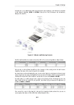
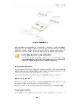
Consider a single NetDefend Firewall connected to two external ISPs,
ISP1
and
ISP2
.
ISP1
provides
Internet connection to the internal network for
Department A
and connects to the NetDefend
Firewall via the physical interface
If1
.
ISP2
provides Internet connection to the internal network for
Department B
and connects via the
physical interface
If2
. For administration purposes it is decided that the NetDefend Firewall is to
be divided into 2 virtual systems, one for each ISP.
This is done by creating two dedicated routing tables.
pbr1
is created to handle traffic for
ISP1
and
Department A
.
pbr2
is created to handle traffic for
ISP2
and
Department B
. This arrangement is
illustrated in the diagram below.
Chapter 4: Routing
323
Summary of Contents for NetDefendOS
Page 30: ...Figure 1 3 Packet Flow Schematic Part III Chapter 1 NetDefendOS Overview 30 ...
Page 32: ...Chapter 1 NetDefendOS Overview 32 ...
Page 144: ...Chapter 2 Management and Maintenance 144 ...
Page 284: ...Chapter 3 Fundamentals 284 ...
Page 392: ...Chapter 4 Routing 392 ...
Page 419: ... Host 2001 DB8 1 MAC 00 90 12 13 14 15 5 Click OK Chapter 5 DHCP Services 419 ...
Page 420: ...Chapter 5 DHCP Services 420 ...
Page 573: ...Chapter 6 Security Mechanisms 573 ...
Page 607: ...Chapter 7 Address Translation 607 ...
Page 666: ...Chapter 8 User Authentication 666 ...
Page 775: ...Chapter 9 VPN 775 ...
Page 819: ...Chapter 10 Traffic Management 819 ...
Page 842: ...Chapter 11 High Availability 842 ...
Page 866: ...Default Enabled Chapter 13 Advanced Settings 866 ...
Page 879: ...Chapter 13 Advanced Settings 879 ...

