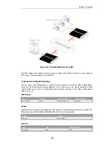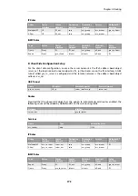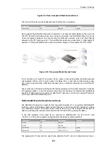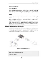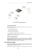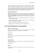
The diagram above illustrates how switch route interconnections for one routing table are
completely separate from the switch route interconnections for another routing table. By using
different routing tables in this way we can create two separate transparent mode networks.
The routing table used for an interface is decided by the
Routing Table Membership
parameter for
each interface. To implement separate transparent mode networks, interfaces must have their
Routing Table Membership
reset.
By default, all interfaces have
Routing Table Membership
set to be
all
routing tables. Also by
default, one
main
routing table always exists and once an additional routing table has been
defined, the
Membership
for any interface can then be set to be that new table.
Transparent Mode with VLANs
If transparent mode is being set up for all hosts and users on a VLAN then the technique
described above of using multiple routing tables also applies. A dedicated routing table should
be defined for each VLAN ID and switch routes should then be defined in that routing table
which refer to the VLAN interfaces. The reason for doing this is to restrict the ARP requests to the
interfaces on which the VLAN is defined.
To better explain this, let us consider a VLAN
vlan5
which is defined on two physical interfaces
called
if1
and
if2
. Both physical interfaces have switch routes defined so they operate in
transparent mode. Two VLAN interfaces with the same VLAN ID are defined on the two physical
interfaces and they are called
vlan5_if1
and
vlan5_if2
.
For the VLAN to operate in transparent mode we create a routing table with the ordering set to
only
and which contains the following 2 switch routes:
Network
Interface
all-nets
vlan5_if1
all-nets
vlan5_if2
Instead of creating individual entries, an interface group could be used in the above routing
table.
No other non-switched routes should be in this routing table because traffic that follows such
routes will be tagged incorrectly with the VLAN ID.
Finally, we must associate this routing table with its VLAN interface by defining a
Policy Based
Routing Rule
.
Enabling Transparent Mode Directly on Interfaces
The recommended way to enable transparent mode is to add switch routes, as described above.
An alternative method is to enable transparent mode directly on an interface (a check box for
this is provided in the graphical user interfaces). When enabled in this way, default switch routes
are automatically added to the routing table for the interface and any corresponding non-switch
Chapter 4: Routing
383
Summary of Contents for NetDefendOS
Page 30: ...Figure 1 3 Packet Flow Schematic Part III Chapter 1 NetDefendOS Overview 30 ...
Page 32: ...Chapter 1 NetDefendOS Overview 32 ...
Page 144: ...Chapter 2 Management and Maintenance 144 ...
Page 284: ...Chapter 3 Fundamentals 284 ...
Page 392: ...Chapter 4 Routing 392 ...
Page 419: ... Host 2001 DB8 1 MAC 00 90 12 13 14 15 5 Click OK Chapter 5 DHCP Services 419 ...
Page 420: ...Chapter 5 DHCP Services 420 ...
Page 573: ...Chapter 6 Security Mechanisms 573 ...
Page 607: ...Chapter 7 Address Translation 607 ...
Page 666: ...Chapter 8 User Authentication 666 ...
Page 775: ...Chapter 9 VPN 775 ...
Page 819: ...Chapter 10 Traffic Management 819 ...
Page 842: ...Chapter 11 High Availability 842 ...
Page 866: ...Default Enabled Chapter 13 Advanced Settings 866 ...
Page 879: ...Chapter 13 Advanced Settings 879 ...

