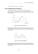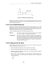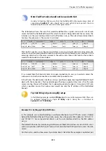
Figure 10.12. Stickiness and Connection-rate
Regardless which algorithm is chosen, if a server goes down, traffic will be sent to other servers.
And when the server comes back online, it can automatically be placed back into the server farm
and start getting requests again.
10.4.5. Server Health Monitoring
SLB uses
Server Health Monitoring
to continuously check the condition of the servers in an SLB
configuration. SLB can monitor different OSI layers to check the condition of each server.
Regardless of the algorithms used, if a server is deemed to have failed, SLB will not open any
more connections to it until the server is restored to full functionality.
D-Link Server Load Balancing provides the following monitoring modes:
ICMP Ping
This works at OSI layer 3. SLB will ping the IP address of each individual
server in the server farm. This will detect any failed servers.
TCP Connection
This works at OSI layer 4. SLB attempts to connect to a specified port on
each server. For example, if a server is specified as running web services
on port 80, the SLB will send a TCP SYN request to that port. If SLB does
not receive a TCP SYN/ACK back, it will mark port 80 on that server as
down. SLB recognizes the conditions
no response
,
normal response
or
closed port response
from servers.
10.4.6. Setting Up SLB_SAT Rules
The key component in setting up SLB are IP rules that have
SLB_SAT
as the action. The steps that
should be followed for setting up such rules are:
1.
Define an IP address object for each server for which SLB is to be enabled.
2.
Define an IP address group object which includes all these individual objects.
3.
Define an
SLB_SAT
rule in the IP rule set which refers to this IP address group and where all
other SLB parameters are defined.
4.
Define a further rule that duplicates the source/destination interface/network of the
SLB_SAT
rule that permits the traffic through. This could be one rule or a combination of
rules using the actions:
•
Allow
•
NAT
Chapter 10: Traffic Management
812
Summary of Contents for NetDefendOS
Page 30: ...Figure 1 3 Packet Flow Schematic Part III Chapter 1 NetDefendOS Overview 30 ...
Page 32: ...Chapter 1 NetDefendOS Overview 32 ...
Page 144: ...Chapter 2 Management and Maintenance 144 ...
Page 284: ...Chapter 3 Fundamentals 284 ...
Page 392: ...Chapter 4 Routing 392 ...
Page 419: ... Host 2001 DB8 1 MAC 00 90 12 13 14 15 5 Click OK Chapter 5 DHCP Services 419 ...
Page 420: ...Chapter 5 DHCP Services 420 ...
Page 573: ...Chapter 6 Security Mechanisms 573 ...
Page 607: ...Chapter 7 Address Translation 607 ...
Page 666: ...Chapter 8 User Authentication 666 ...
Page 775: ...Chapter 9 VPN 775 ...
Page 819: ...Chapter 10 Traffic Management 819 ...
Page 842: ...Chapter 11 High Availability 842 ...
Page 866: ...Default Enabled Chapter 13 Advanced Settings 866 ...
Page 879: ...Chapter 13 Advanced Settings 879 ...

