MAX32600 User’s Guide
Communication Peripherals
7.1 I²C
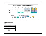
PCLK
F
I2C
I²C
DUTY
F
HOLD
T
RC
Filt CLK Divisor
SCL Hi
SCL Lo
3
100
0.67
1
1000
2
1
18
Note
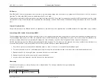
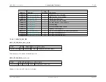
Explanation of
SCL Clock Configuration Common Calculations
values:
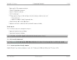
• PCLK = Peripheral Clock (MHz)
• F
I2C
= I
2
C Frequency (KHz)
• I²C
DUTY
= I
2
C Duty Cycle (H/L)
• F
HOLD
= I
2
C Hold (us)
• T
RC
= RC Rise Time (ns)
• Filt CLK Divisor =
• SCL Hi =
• SCL Lo =
7.1.7
Communication and Data Transfer
7.1.7.1
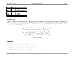
FIFO-Based I²C Master
The FIFO-based I
2
C engine implements a packetized interface to slave devices. This interface supports multi-master environments, 10-bit addressing, and System
Management Bus (SMbus) protocol.
Sixteen-byte FIFOs are provided on each master peripheral for both Tx and Rx. The data is tagged prior to enqueuing to allow decoupling of firmware execution from
I
2
C operation. A full complement of FIFO status is available for firmware monitoring and interrupt generation.
The user must define the filter clock frequency, which is typically two to four times faster than the target SCL frequency. The target SCL frequency and duty cycle are
set by defining the low and high system clock limits of the SCL clock (i.e., SCL low time and SCL high time). If operating in a high-speed environment, the user must
define two sets of clock control registers for normal-speed as well as high-speed.
Note
Pullup delays, input filtering delays, and multi-master clock synchronization affect the observed SCL frequency on the I
2
C bus.
Rev.1.3 April 2015
Maxim Integrated
Page 228


