MAX32600 User’s Guide
Communication Peripherals
7.4 USB Device Interface
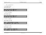
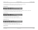
• 1: Connect internal pullup resistor between DPLUS and VBUS.
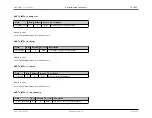
USB_DEV_CN.ulpm
Field
Bits
Default
Access
Description
ulpm
4
0
R/W
USB Low Power Mode
• 0: USB transceiver in normal operation
• 1: USB transceiver will enter a low power mode
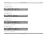
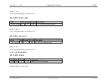
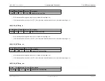
USB_DEV_CN.urst
Field
Bits
Default
Access
Description
urst
5
0
R/W
USB Device Controller Reset
• 0: USB device controller is released to run normally.
• 1: USB device controller is held in reset (until this bit is cleared back to 0 by firmware)
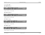
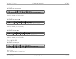
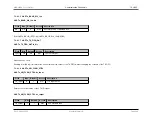
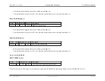
USB_DEV_CN.vbgate
Field
Bits
Default
Access
Description
vbgate
6
0
R/W
VBUS Gate
• 0: CONNECT operation is independent of VBUS status
• 1: CONNECT operation is performed conditionally depending on presence of VBUS voltage
Rev.1.3 April 2015
Maxim Integrated
Page 307

