Customizing the Board
8-5
8.4 SUPERVISION FEATURES
The TEK-CPCI-1003 provides a set of programmable I/O registers to setup the Intel PIIX4
(I/O addresses 4030h to 4037h) and the XILINX CPLD (I/O addresses programmable at
190h-193h, 290h-293h or 390h-393h using the AWARD Chipset Features Setup).
Only register bits needed to program the power fail detection and watchdog functions are
described below.
8.4.1 Power Fail Monitoring
The power failure detector status can be readout from one bit of the system register located
at the address 4031h (See table below). The detection conforms to the following conditions
(* = active low signal):
1.
It always monitors the +5V power supply. When it drops below 4.65V (typical), the
system is reset.
2.
It can monitor the onboard battery. When the battery is in a low condition (below 2.9V
typical), the PFO* (power fail output) signal goes low. The status of the PFO* signal
can be read at I/O address 4031h, bit 1 (0 = failed, 1 = good). The PFO* signal can
also be connected to the IOCHK* signal to generate an NMI (non-maskable interrupt)
by setting W3 jumper. To setup W3, please refer to Section 9 –
Setting Jumpers
.
An interrupt handler can then service the interrupt. If you choose not to generate an NMI,
you can use an algorithm to detect a low battery condition and respond accordingly.
Register
Bit #
Function
Software Programming
4030h
0-7
Reserved
Reserved
4031h
0, 2-7
Reserved
Reserved
1
Power Fail Output (Internal/External
Battery or External Power Source)
Read: 0 = Failed, 1 = Good
4032h
0, 2-7
Reserved
Reserved
1
Watchdog Stage 1 Status
Read: 0 = Timed out, 1 = Normal
4034h
0-7
Reserved
Reserved
4035h
0-1, 4-7
Reserved
Reserved
2
Watchdog enable
Write: 1 = Disable, 0 = Enable
3
Watchdog reset
Write: 1-0-1 (toggle) to activate
the watchdog (when enabled)
4036h
0-7
Reserved
Reserved
4037h
0-7
Reserved
Reserved
For more information, contact the Technical Support department
Summary of Contents for TEK-CPCI 1003
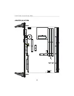
Page 15: ...TEK CPCI 1003 Technical Reference Manual 5 4 5 1 CONNECTOR LOCATION...
Page 22: ...FEATURE DESCRIPTION 7 ONBOARD FEATURES...
Page 51: ...TEK CPCI 1003 Technical Reference Manual 9 2 JUMPER LOCATION...
Page 52: ...Setting Jumpers 9 3 JUMPER SETTINGS Table 1...
Page 53: ...TEK CPCI 1003 Technical Reference Manual 9 4 JUMPER SETTINGS TABLE 2...
Page 67: ...SOFTWARE SETUPS 12 AWARD SETUP PROGRAM 13 UPDATING THE BIOS WITH UPGBIOS 14 VT100 MODE...
Page 95: ...C 1 C BOARD DIAGRAMS C 1 ASSEMBLY TOP DIAGRAM...


