Synergy Controller Technical Manual, Revision H
Page 131
♦
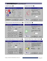
Wait For:
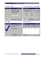
The Waitfor step holds program execution until the specified conditions are met. Those
conditions can be setpoints, a time interval or external digital inputs.
Waitfor steps can wait on one or more channels values. When executing a Waitfor step, the program
will not advance until the actual value (temperature, humidity, etc.) for that channel goes above or
below the Waitfor value. The direction the actual must travel is determined at the very start of the step.
If the actual value is less than the Waitfor value when the step begins, then the step will wait until the
actual value is greater than the Waitfor value. If the actual value is greater than the Waitfor value
when the step begins, then the step will wait for the actual value to be less than or equal to the Waitfor
value.
Waitfor steps can also wait for a specified time. If the time in hours, minutes and seconds are
specified in the Waitfor step, then the controller will hold on the step for that time after all other
conditions are met. The timer will not start counting down until all of the specified channel values are
reached, and any specified digital inputs are reached. Once the conditions are met, the Waitfor time
will count down and then the controller will continue to the next step.
As mentioned above Waitfor steps can also wait for any of the controller’s sixteen digital inputs. Digital
inputs can be wired to the Synergy Controller to indicate one or more user states, such as a unit-
under-test power up during a test. The controller can be set to ignore the input (Don’t care), or to wait
for the input to be on or off (closed or open). Only digital inputs that are not ignored are checked. By
default, all inputs are ignored unless specified.
♦
Auto Start:
The Auto Start step is used to automatically start the chamber. The profile can either
start in a relative time (i.e. ten hours and five minutes from when the program is started) or at an
absolute day and time (i.e. Tuesday, November 4th, 2003 at 7:30 AM). When you add an Auto Start
step to a profile you specify a relative or absolute time.
♦
Stop:
The Stop step is used at the end of a profile to specify what to do at the end of a profile. The
chamber can either shut down and turn off all the outputs (the chamber will gradually return to ambient
conditions), or the chamber can go into steady state and run until manually stopped. If the chamber
returns to steady state mode, the last setpoints of the profile will be used as the steady state setpoints.
♦
Pause:
The Pause step is used to put the Program in thee Paused State. The chamber will continue
to run in the Paused state indefinitely. To continue to the next step the Operator can press the Run
button or the Run command can be from a computer interface.
Synergy Manager can be used to create profiles for the Synergy Controller on your PC where they can be
viewed graphically, stored and archived. Synergy Manager is Tidal Engineering’s PC application designed to
program, monitor and control multiple environmental test chambers. Synergy Manager can save profiles in
the Synergy Controller VPL format so they can be copied to and then run on the controller. The full version
of Synergy Manager can be used to transfer programs to the controller thru a network as well as thru GPIB
and RS-232 connections. See the
of this technical manual or the Synergy
Manager technical manual for more details. Synergy Manager is available for download from
www.tidaleng.com/download.htm.
Summary of Contents for Synergy Compact
Page 14: ...Synergy Controller Technical Manual Revision H Page 14 2 0 SPECIFICATIONS 2 1 Data Sheet...
Page 71: ...Synergy Controller Technical Manual Revision H Page 71...
Page 106: ...Synergy Controller Technical Manual Revision H Page 106...
Page 123: ...Synergy Controller Technical Manual Revision H Page 123...
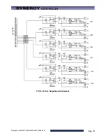
Page 141: ...Synergy Controller Technical Manual Revision H Page 141 TE1151 6 Triac Output Board Schematic...
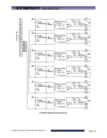
Page 142: ...Synergy Controller Technical Manual Revision H Page 142 TE1708 6 Relay Board Schematic...
Page 188: ...Synergy Controller Technical Manual Revision H Page 188...
Page 274: ...Synergy Controller Technical Manual Revision H Page 274 Synergy Controller Step Syntax...
Page 294: ...Synergy Controller Technical Manual Revision H Page 294...
Page 312: ...Synergy Controller Technical Manual Revision H Page 312...
Page 345: ...Synergy Controller Technical Manual Revision H Page 345...
Page 346: ...Synergy Controller Technical Manual Revision H Page 346...

