Command Channel Response Frames
The iVu responds to all request frames with one or two responses depending on the type of command.
Do commands
All do commands are followed by one response that identifies the command status. For example:
>>
do trigger
\x0D\x0A
<<
OK\x0D\x0A
Get commands
All get commands are followed by two responses: the first identifies the status of the command, and the second
contains the retrieved information. For example:
>>
get bcr_input comparedata
\x0D\x0A
<<
OK\x0D\x0A
<<
"012345ABCDEF"\x0D\x0A
Set commands
All set commands are followed by one response that identifies the command status. For example:
>>
set bcr_input comparedata "012345ABCDEF"
\x0D\x0A
<<
OK\x0D\x0A
Command Channel Command Status
The command status is either OK or ERROR. If OK, then the command has fully and successfully completed. If an error is
returned it is in the form ERROR nnnnn_ERROR_IDENTIFIER (for example ERROR 10001_COMMAND_NOT_RECOGNIZED).
Refer to
Command Channel Error Codes
on page 98 for a list of errors.
8.4.2 Conventions Used for Examples
There are a number of command channel examples included here, and the following are the conventions used in the
examples:
•
All examples use <CR><LF> for the end-of-frame delimiter, and this delimiter is always denoted in hex (\x0D\x0A)
since that is what is displayed in the iVu logs and, for example, the Port Status screen.
•
All commands are in bold text.
•
For each example, a command request to the iVu sensor is prefaced with a >>, and a command response frame
from the iVu sensor is prefaced by a << as shown below. These are only used to make the documentation clearer.
>>
get info companyname
\x0D\x0A
<<
OK\x0D\x0A
<<
"Banner Engineering Corp."\x0D\x0A
8.4.3 Examples
How to Trigger the Sensor and Retrieve Inspection Data using the Command Channel
This example is based on a sort inspection. To trigger the sensor and retrieve inspection data, do the following
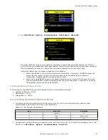
1. Make sure that the Command Channel is enabled using either Ethernet or Serial I/O ( Main Menu > System >
Communications > Command Channel > Connection ).
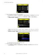
2. Set Trigger to Command. Go to the Main Menu > Imager > Trigger screen, and from the drop-down select
Command.
3. Issue a trigger command as follows:
>>
do trigger
\x0D\x0A
<<
OK\x0D\x0A
4. Check that the inspection passed.
>>
get inspection status
\x0D\x0A
<<
OK\x0D\x0A
<<
Pass\x0D\x0A
iVu Plus TG Gen2 Image Sensor
90
www.bannerengineering.com - Tel: 763.544.3164


