


249
CHAPTER 12 16-BIT INPUT/OUTPUT TIMER
■
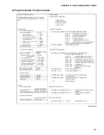
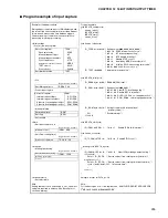
Program example of output compare
(Continued)
Example of setting procedure
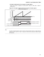
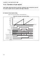
2-channel independent output compare operation
(7FFFF, BFFFF), interrupt generation, no compare
clear
Program example
void OUTPUT01_sample(void)
{
freerun_initial();
OUTPUT01_initial();
OUTPUT01_start();
freerun_start();
}
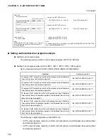
<Initial setting>
•
Control free-running timer
•
Control output compare
•
Interrupt related
void freerun_initial(void)
{
IO_TCCS.word = 0x0020; /* Setting value=0000_0000_0010_0000 */
/* bit15 = 0
ECKE internal clock source*/
/* bit7 = 0
IVF interrupt request flag */
/* bit6 = 0
Enable IVFE interrupt */
/* bit5 = 1
Disable STOP count */
/* bit4 = 0
Initialize by MODE reset, clear bit */
/* bit3 = 0
Initialize SCLR free-running timer value */
/* bit2-0 = 000 CLK2-0 count clock
φ/
4=32MHz/4 */
IO_TCDT = 0x0000;
/* Initialize timer data value */
}
void OUTPUT01_initial(void)
{
IO_OCS01.word = 0x0C00;/* Setting value=0000_1100_0000_0000 */
/* bit15-13 = 000
Undefined bit*/
/* bit12 = 0
Reverse CMOD ch.0,ch.1 level */
/* bit11-10 = 11
Enable OTE1,OTE0 pin output */
/* bit9-8 = 00
OTD1,OTD0 compare pin output 0 */
/* bit7-6 = 00
Clear ICP1,ICP0 output compare flag */
/* bit5-4 = 00
Disable
ICE1,ICE0 output compare interrupt */
/* bit3-2 = 00
Undefined bit */
/* bit1-0 = 00
Disable CST1,CST0 compare
operation */
IO_OCCP0 = BFFF;
/* Set Compare register ch.0 */
IO_OCCP1 = 7FFF;
/* Set Compare register ch.1 */
IO_ICR08.byte = 0x00;
/* Set output compare ch.0 interrupt level
(arbitrary value) */
IO_ICR09.byte = 0x00;
/* Set output compare ch.1 interrupt level
(arbitrary value) */
__EI();
/* Enable interrupt */
}
<Start>
•
Start output compare
•
Start free-running timer
void OUTPUT01_start(void)
{
IO_OCS01.word = 0x0C30;/* bit5-4 = 11
Enable ICE1,ICE0 output compare
interrupt */
IO_OCS01.word = 0x0C33;/* bit1-0 = 11
Enable CST1,CST0 compare
operation */
}
void freerun_start(void)
{
IO_TCCS.bit.STOP = 0;
/* bit4 = 0
Enable STOP count */
}
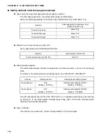
Set control register
TCCS
Clock selection>>
.ECKE
Interrupt request flag>>
.IVF
Interrupt request enable>>
.IVFE
Count operation>>
.STOP
Initialization condition of timer>>
.MODE
TCDT clear>>
.SCLR
Count clock>>
.CLK2-0
Set timer data value
TCDT
Register name. bit name
Set control register
OCS01
Reverse operation of pin
output level>>
.CMOD
Pin output enable>>
.OTE1,OTE0
Specify pin output level>>
.OTD1,OTD0
Interrupt request flag>>
.ICP1,ICP0
Interrupt request enable>> .ICE1,ICE0
Set operation enable>>
.CST1.CST0
Set compare value ch.0
OCCP0
Set compare value ch.1
OCCP1
Set interrupt level
ICR08
Set interrupt level
ICR09
Set I flag
(CCR)
Register name. bit name
Interrupt control
OCS01 .ICE1.ICE0
Start compare operation
OCS01 .CST1.CST0
Register name. bit name
Start count operation
TCCS .STOP
Summary of Contents for MB90480 Series
Page 2: ......
Page 4: ......
Page 10: ...vi ...
Page 128: ...106 CHAPTER 4 RESET ...
Page 174: ...152 CHAPTER 6 LOW POWER CONSUMPTION MODE ...
Page 198: ...176 CHAPTER 7 MODE SETTING ...
Page 220: ...198 CHAPTER 9 TIMEBASE TIMER ...
Page 238: ...216 CHAPTER 11 WATCH TIMER ...
Page 280: ...258 CHAPTER 12 16 BIT INPUT OUTPUT TIMER ...
Page 406: ...384 CHAPTER 17 8 10 BIT A D CONVERTER ...
Page 478: ...456 CHAPTER 20 CHIP SELECTION FACILITY ...
Page 494: ...472 CHAPTER 21 ADDRESS MATCH DETECTION FUNCTION ...
Page 498: ...476 CHAPTER 22 ROM MIRROR FUNCTION SELECTION MODULE ...
Page 526: ...504 CHAPTER 23 2M 3M BIT FLASH MEMORY ...
Page 536: ...514 CHAPTER 24 EXAMPLES OF MB90F481B MB90F482B MB90F488B MB90F489B SERIAL PROGRAMMING ...
Page 570: ...548 CHAPTER 25 PWC TIMER ONLY MB90485 SERIES ...
Page 688: ......


