


370
CHAPTER 17 8/10-BIT A/D CONVERTER
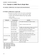
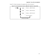
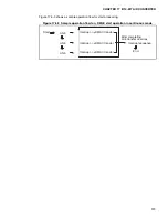
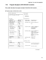
17.5.1 Example of
μ
DMAC Start in Single Mode
An example of
μ
DMAC start in the single mode is described below.
■
Example of
μ
DMAC start in single mode
An example of start operation is based on the conditions described below:
•
Conversion finishes after conversion up to analog input (AN1 to AN3)
•
Conversion data is transferred to addresses 200
H
to 206
H
sequentially
•
Start by software
•
The highest interrupt level is used
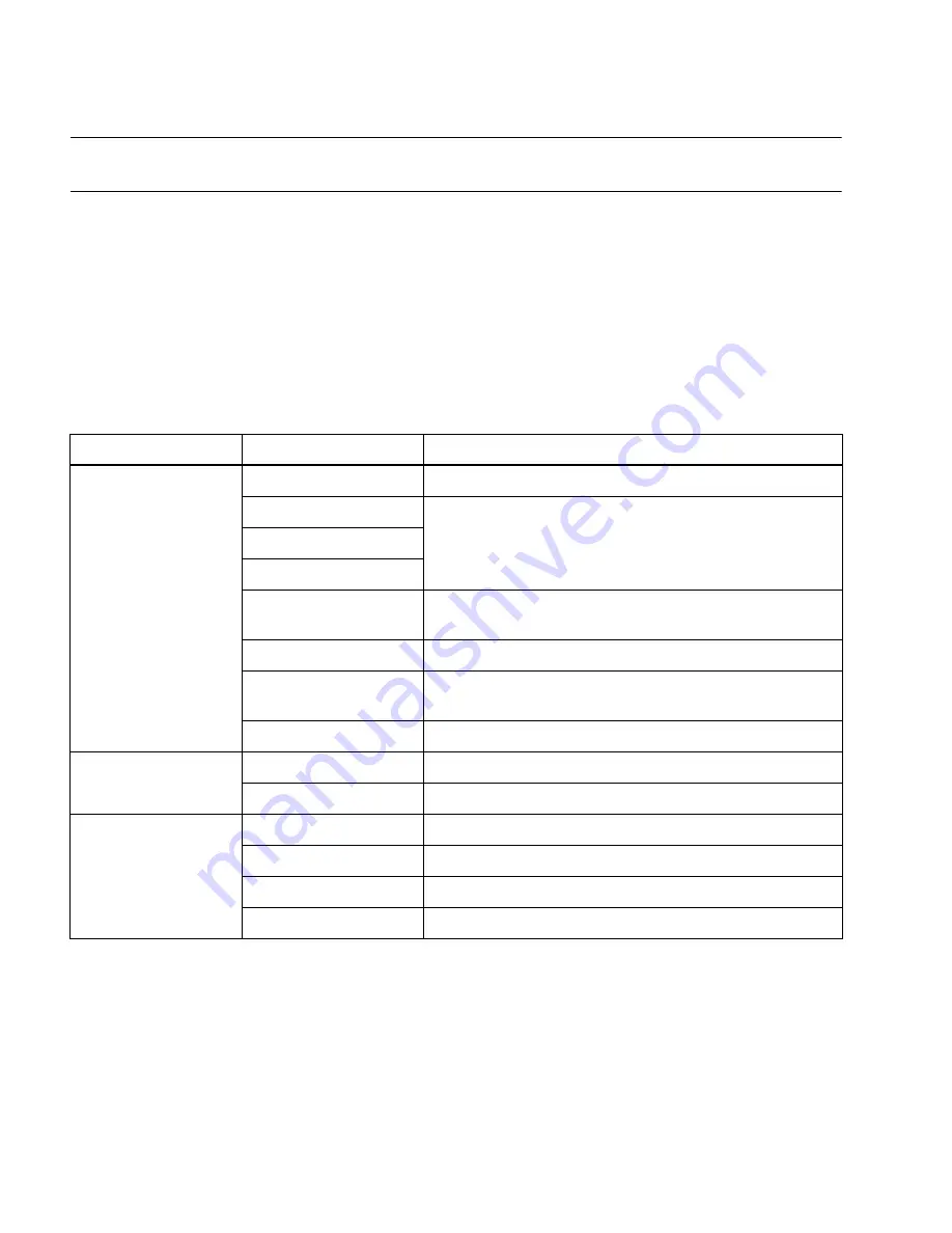
Setting item
Sample program
Operation
μ
DMAC setting
MOV ICR14,#00H
Sets highest interrupt level and enables interrupts
MOV BAPL,#00H
Address to transfer conversion data
MOV BAPM,#02H
MOV BAPH,#00H
MOV DMACS,#18H
Set DMA control status register (Transfers word data and
increments the destination address after transfer)
MOV IOA,#48H
Stores A/D conversion results in registers
MOV DCT,#03H
Performs three transfers, matching the number of
conversions
MOVW DERL,#8000H
Setting for the
μ
DMAC enable register (EN15)
A/D converter setting
MOV ADCS1,#0BH
Single mode, start channel AN1, end channel AN3
MOV ADCS2,#A2H
Software start, A/D conversion start
μ
DMAC end
sequence
WBTC io ADCS2:7
Determines end of A/D conversion
MOV ADCS2,#000H
Resource interrupt clear
MOVW DSRL,#0000H
μ
DMAC status register clear
RETI
Reset from interrupt
ICR14: Interrupt control register
BAPL: Buffer address pointer lower
BAPM: Buffer address pointer middle
BAPH: Buffer address pointer higher
ISCS: Status register
IOA:
Address register
DCT:
Data counter
Summary of Contents for MB90480 Series
Page 2: ......
Page 4: ......
Page 10: ...vi ...
Page 128: ...106 CHAPTER 4 RESET ...
Page 174: ...152 CHAPTER 6 LOW POWER CONSUMPTION MODE ...
Page 198: ...176 CHAPTER 7 MODE SETTING ...
Page 220: ...198 CHAPTER 9 TIMEBASE TIMER ...
Page 238: ...216 CHAPTER 11 WATCH TIMER ...
Page 280: ...258 CHAPTER 12 16 BIT INPUT OUTPUT TIMER ...
Page 406: ...384 CHAPTER 17 8 10 BIT A D CONVERTER ...
Page 478: ...456 CHAPTER 20 CHIP SELECTION FACILITY ...
Page 494: ...472 CHAPTER 21 ADDRESS MATCH DETECTION FUNCTION ...
Page 498: ...476 CHAPTER 22 ROM MIRROR FUNCTION SELECTION MODULE ...
Page 526: ...504 CHAPTER 23 2M 3M BIT FLASH MEMORY ...
Page 536: ...514 CHAPTER 24 EXAMPLES OF MB90F481B MB90F482B MB90F488B MB90F489B SERIAL PROGRAMMING ...
Page 570: ...548 CHAPTER 25 PWC TIMER ONLY MB90485 SERIES ...
Page 688: ......


