5-20
BUS TRANSACTIONS AND OPERATIONS
5.3.4.1.
[SPLIT] BUS LOCK
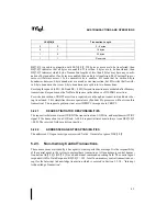
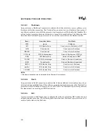
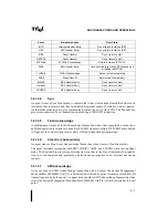
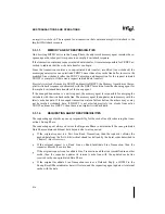
All variables that cannot be cache locked are locked using the standard [split] bus lock operation.
A Pentium Pro processor [split] bus locked operation (read-modify-write or RMW) involves 1
or 2 memory read transactions followed by 1 or 2 memory write transactions to the same ad-
dress. When any agent issues a RMW operation, it asserts the LOCK# signal in the Request
Phase and keeps it active during the entire Lock Operation. In a split bus locked operation, the
agent asserts Split Lock (SPLCK#) in the first transaction to indicate a split operation. During a
RMW operation the agent always deasserts Defer Enable (DEN#) for all transactions in the op-
eration. The first transaction of the RMW operation may have DEFER# asserted, which will re-
try the entire RMW operation (regardless of the response). No transaction in the RMW operation
after the first read transaction may have DEFER# asserted.
The RMW Operation is successfully completed when the agent successfully completes all mem-
ory transactions. Successful completion occurs when the last transaction of the RMW operation
passes its Error Phase. The requestor retains ownership of the bus by keeping LOCK# active un-
til the last transaction successfully completes. The RMW Operation is prematurely aborted and
retried if the first read transaction receives an AERR# assertion in the Error Phase or DEFER#
assertion in the Snoop Phase. After a premature abortion, the agent issuing the lock operation
must ignore any data returned during Data Phase, deassert LOCK#, re-arbitrate for the bus
(deassert its BREQn# signal if active) and reissue the first transaction.
During the memory read transactions, if other writeback cache agents contain the variable in
Modified state, they supply the data via the implicit writeback mechanism. If the lock variable
is contained in Modified state inside the requestor, it performs self-snooping after the locked
transaction is issued on the bus and evicts the cache line via the implicit writeback mechanism.
As explained in Chapter 4, Bus Protocol, if DEFER# assertion is not over-ridden by HITM# as-
sertion, the agent asserting DEFER# must drive a Retry Response in the Response Phase to force
a retry. If DEFER# assertion is overridden by HITM# assertion, the responding agent drives an
implicit writeback response, and the Data Phase completes with an implicit writeback from the
snooping agent. In either case, the lock sequence is aborted and retried.
The entire RMW Operation fails if any one of the bus locked transactions receives a hard error/
deferred response or AERR# assertion beyond the retry limit of the agent, or if any one of the
second to fourth transactions receives DEFER# assertion. These are protocol violations. As ex-
plained in Chapter 4, Bus Protocol, AERR# assertion causes an arbitration reset sequence. If
AERR# gets asserted on the second to fourth transaction within the retry limit of the agent, the
retrying agent must be guaranteed bus ownership to guarantee indivisibility of the lock opera-
tion. The bus protocol requires the retrying agent to arbitrate for the bus two clocks before all
other agents.
Summary of Contents for Pentium Pro Family
Page 17: ...1 Component Introduction ...
Page 26: ...2 Pentium Pro Processor Architecture Overview ...
Page 27: ......
Page 36: ...3 Bus Overview ...
Page 62: ...4 Bus Protocol ...
Page 105: ...5 Bus Transactions and Operations ...
Page 126: ...6 Range Registers ...
Page 131: ...7 Cache Protocol ...
Page 135: ...8 Data Integrity ...
Page 148: ...9 Configuration ...
Page 161: ...10 Pentium Pro Processor Test Access Port TAP ...
Page 172: ...11 Electrical Specifications ...
Page 201: ...12 GTL Interface Specification ...
Page 229: ...13 3 3V Tolerant Signal Quality Specifications ...
Page 233: ...14 Thermal Specifications ...
Page 239: ...15 Mechanical Specifications ...
Page 241: ...15 2 MECHANICAL SPECIFICATIONS s Figure 15 1 Package Dimensions Bottom View ...
Page 252: ...16 Tools ...
Page 260: ...16 8 TOOLS Figure 16 4 Generic MP System Layout for Debug Port Connection ...
Page 264: ...17 OverDrive Processor Socket Specification ...
Page 290: ...A Signals Reference ...
Page 320: ...Index ...
Page 328: ......


