3-24
BUS OVERVIEW
The Pentium Pro processor asserts FERR# when it detects an unmasked floating-point error.
FERR# is included for compatibility with systems using DOS-type floating-point error
reporting.
If the IGNNE# input signal is asserted, the Pentium Pro processor ignores a numeric error and
continues to execute non-control floating-point instructions. If the IGNNE# input signal is deas-
serted, the Pentium Pro processor freezes on a non-control floating-point instruction if a previ-
ous instruction caused an error.
If the A20M# input signal is asserted, the Pentium Pro processor masks physical address bit 20
(A20#) before looking up a line in any internal cache and before driving a memory read/write
transaction on the bus. Asserting A20M# emulates the 8086 processor’s address wraparound at
the one Mbyte boundary. A20M# must only be asserted when the processor is in real mode.
A20M# is not used to mask external snoop addresses.
The IGNNE# and A20M# signals are valid at all times. These signals are normally not guaran-
teed recognition at specific boundaries. However, to guarantee recognition of A20M#, and the
trailing edge of IGNNE# following an I/O write instruction, these signals must be valid in the
Response Phase of the corresponding I/O Write bus transaction.
The A20M# and IGNNE# signals have different meanings during a reset. A20M# and IGNNE#
are sampled on the active to inactive transition of RESET# to determine the multiplier for the
internal clock frequency, as described in Chapter 9, Configuration.
System Management Interrupt is asserted asynchronously by system logic. On accepting a Sys-
tem Management Interrupt, the Pentium Pro processor saves the current state and enters SMM
mode. It issues an SMI Acknowledge Bus transaction and then begins program execution from
the SMM handler.
3.4.10.
Diagnostic Signals
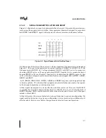
The BP[3:2]# signals are the System Support group Breakpoint signals. They are outputs from
the Pentium Pro processor that indicate the status of breakpoints.
The BPM[1:0]# signals are more System Support group breakpoint and performance monitor
signals. They are outputs from the Pentium Pro processor that indicate the status of breakpoints
and programmable counters used for monitoring Pentium Pro processor performance.
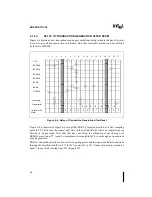
Table 3-19. Diagnostic Support Signals
Type
Signal Names
Number
Breakpoint Signals
BP[3:2]#
2
Performance Monitor
BPM[1:0]#
2
Boundary Scan/Test Access
TCK, TDI, TDO, TMS, TRST#
5
Summary of Contents for Pentium Pro Family
Page 17: ...1 Component Introduction ...
Page 26: ...2 Pentium Pro Processor Architecture Overview ...
Page 27: ......
Page 36: ...3 Bus Overview ...
Page 62: ...4 Bus Protocol ...
Page 105: ...5 Bus Transactions and Operations ...
Page 126: ...6 Range Registers ...
Page 131: ...7 Cache Protocol ...
Page 135: ...8 Data Integrity ...
Page 148: ...9 Configuration ...
Page 161: ...10 Pentium Pro Processor Test Access Port TAP ...
Page 172: ...11 Electrical Specifications ...
Page 201: ...12 GTL Interface Specification ...
Page 229: ...13 3 3V Tolerant Signal Quality Specifications ...
Page 233: ...14 Thermal Specifications ...
Page 239: ...15 Mechanical Specifications ...
Page 241: ...15 2 MECHANICAL SPECIFICATIONS s Figure 15 1 Package Dimensions Bottom View ...
Page 252: ...16 Tools ...
Page 260: ...16 8 TOOLS Figure 16 4 Generic MP System Layout for Debug Port Connection ...
Page 264: ...17 OverDrive Processor Socket Specification ...
Page 290: ...A Signals Reference ...
Page 320: ...Index ...
Page 328: ......


