SD20-G Series
227
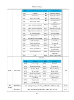
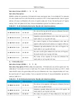
register in R area;
MOVWDP D-3 P101
Po101=-3
Immediate operand transfers to no.101 register in P area;
MOVWRP R10 P101
Po101=R10
No.10 register of R area transfers to no.101 register of
Parea;
MOVWPP P1 P2
Po002=Po001
Data transfer in P area;
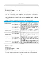
(2)32-bit Move Instruction
Instruction Format
:
[MOVD□□ X Y]
Instruction Description:
:
MOVD is move instruction code,□□ is instruction execution register area, X
is execution operating register address, Y is destination register address; After executing instructions, the
result is Y=X, of which register address of X, Y need dividing into high-low bits to store the data.
□□ can be changed for register area according to practical operation, movable area includes R area, P area
and immediate operand; See details in table 8.1.2;
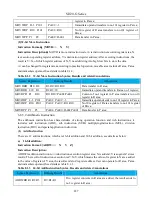
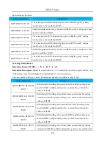
Table 8.1.2 32-bit Move Instruction Syntax, Results and related Annotations
Syntax Expression
Running Results
Annotations
MOVDRR R10 R2
R3 R2=R11 R10
Data transfer in R area;
MOVDDR L10 R1
R2 R1=10
Immediate operand transfers to R area no.1 register;
MOVDPR P1 R10
R11 R10=Po002 Po001
Content of no.1 register in P area transfers to no.10
register in R area;
MOVDDP L-3 P101
Po102 Po101=-3
Immediate operand sends to no.101 register in P area;
MOVDRP R10 P101
Po102 Po101=R11 R10
No.10 register of R area transfers to no.101 register
of Parea;
MOVDPP P1 P3
Po004 Po003=Po002 Po001
Data transfer in P area;
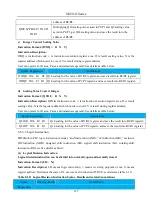
6.8.3.2 Arithmetic Instruction
The arithmetic instruction has characteristics of strong operation function and rich instructions, it
includes add instruction (ADD), sub instruction (SUB), multiplyinginstruction (MUL), division
instruction (DIV) and special application instruction.
(1)
Add Instruction
There are 12 add instructions, which are 16-bit addition and 32-bit addition, see details as below:
a)
16-bit addition:
Instruction Format: [ADDW□□ X Y Z]
Instruction Description:
ADDW is addition instruction,□□ isinstruction execution register area; X is addend; Y is augend; Z stores
results; The result of instruction execution is Z=X+Y, which means the value of register in X area added
to the value of register of Y area, the result sends to Z register address. User can operate for R area, P area
and immediate operand; See details as table 8.1.3
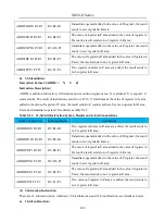
Table 8.1.3 16-bit Add Instruction Syntax, Results and related Annotations
Syntax Expression
Running Results
Annotations
ADDWRR R1 R2 R3
R3=R1+R2
Two register contents in R area are added, the result sends to
no.3 register in R area;
Summary of Contents for SD20-G Series
Page 35: ...SD20 G Series 35 M3 structure Fig 3 1 5 Servo drive structure 3...
Page 36: ...SD20 G Series 36 ML3 structure 118 5 5 7 5 93 297 8 223 118 93 0 5 12 5 7 5 4 M4...
Page 38: ...SD20 G Series 38 M4 structure Approx mass 10 365 kg Fig 3 1 7 Servo drive structure 5...
Page 39: ...SD20 G Series 39 M5 structure Approx msaa 11 1Kg Fig 3 1 8 Servo drive structure 6...
Page 40: ...SD20 G Series 40 M6 structure Approx mass 17 4Kg Fig 3 1 9 Servo drive structure 7...
Page 182: ...SD20 G Series 182 Fig 6 4 44SD20E Cam internal frameworkdiagram...


