SD20-G Series
341
The LRC is calculated by adding together successive 8–bit bytes of the message, discarding any carries, and then
two’s complementing the result.
A procedure for generating an LRC is:
1. Add all bytes in the message, excluding the starting ‘colon’ and ending CRLF. Add them into an 8–bit field, so
that carries will be discarded.
2. Subtract the final field value from FF hex (all 1’s), to produce the ones–complement.
3. Add 1 to produce the twos–complement.
(2) RTU mode
CRC-16 (Cyclical Redundancy Check)
,
please read reference books or ask for the details from Parker..
II Command Type & Format
1 The listing below shows the function codes.
Code
Name
Description
03
Read Holding Registers
Read the binary contents of holding registers in the slave.
(Less than 10 registers once time )
06
Preset Single Register
Preset a value into holding register
16
Preset Multiple Register
Preset values into successive registers (1~120 registers)
Note: In ASCII mode, register number must be less than 40.
In RTU mode, register number must be less than 100.
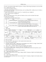
2 Format
(1) ASCII mode
(2) RTU mode
Start
Address
Function
Data
CRC check
End
T1-T2-T3-T4
Servo drive
Address
Function
Code
N data
Low-order
byte of CRC
High-order byte
of CRC
T1-T2-T3-T4
(3) Protocol Converter
It is easy to turn a RTU command into an ASCII command followed by the lists:
1)
Use the LRC replacing the CRC.
2)
Transform each byte in RTU command into a corresponding two byte ASCII. For example: transform 0x03
into 0x30, 0x33 (ASCII code for 0 and ASCII code for 3).
3)
Add a ‘colon’ ( : ) character (ASCII 3A hex) at the beginning of the message.
4)
End with a ‘carriage return – line feed’ (CRLF) pair (ASCII 0D and 0A hex).
So we will introduce RTU Mode in followed part. If you use ASCII mode, you can use the up lists to convert.
3 Parameter address rules
The address of P group parameters is the parameter numbers.
Ex1
:
communication address of Po101:
The parameter numbers of Po101 is 101, the hex format is 0x0065. The address of high bit is 0x00 and the address
of low bit is 0x65.
Ex2
:
communication address of Po407:
The parameter numbers of Po407 is 407, the hex format is 0x0197. The address of high bit is 0x01 and the address
of low bit is 0x97.
Start
Address
Function
Data
LRC check
End
:
(0X3A)
Servo
drive
Address
Function
Code
Data
length
Data
1
…
…
Data
N
High-order
byte of LRC
Low-order
byte of
LRC
Return
(0X0D)
Line Feed
(0X0A)
Summary of Contents for SD20-G Series
Page 35: ...SD20 G Series 35 M3 structure Fig 3 1 5 Servo drive structure 3...
Page 36: ...SD20 G Series 36 ML3 structure 118 5 5 7 5 93 297 8 223 118 93 0 5 12 5 7 5 4 M4...
Page 38: ...SD20 G Series 38 M4 structure Approx mass 10 365 kg Fig 3 1 7 Servo drive structure 5...
Page 39: ...SD20 G Series 39 M5 structure Approx msaa 11 1Kg Fig 3 1 8 Servo drive structure 6...
Page 40: ...SD20 G Series 40 M6 structure Approx mass 17 4Kg Fig 3 1 9 Servo drive structure 7...
Page 182: ...SD20 G Series 182 Fig 6 4 44SD20E Cam internal frameworkdiagram...


