Rev. 3.0, 03/01, page 104 of 390
9.2.14
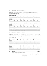
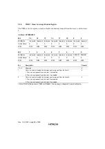
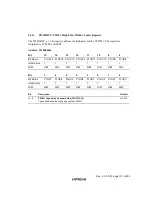
PWM0HPC: PWM 0 High Pulse Width Counter Register
The PWM0HPC, a 16-bit register, defines the high pulse width of PWM 0. The register is
initialized to H’ FFFF at RESET.
Address: H'1000601C
Bit
15
14
13
12
11
10
9
8
Bit Name
P0HC15 P0HC14 P0HC13 P0HC12 P0HC11 P0HC10 P0HC9
P0HC8
Initial Value
1
1
1
1
1
1
1
1
R/W
R/W
R/W
R/W
R/W
R/W
R/W
R/W
R/W
Bit
7
6
5
4
3
2
1
0
Bit Name
P0HC7
P0HC6
P0HC5
P0HC4
P0HC3
P0HC2
P0HC1
P0HC0
Initial Value
1
1
1
1
1
1
1
1
R/W
R/W
R/W
R/W
R/W
R/W
R/W
R/W
R/W
Bit
Description
Default
15 - 0
PWM 0 High Pulse Counter Value (P0HC[15:0])
These bits define the high pulse width of PWM 0.
H’FFFF
9.3
Special Register Programming Sequence
In general, before setting the timer control registers TCR1/TCR0 to start counting, the timer
constant registers TCVR1/TCVR0 should be set first. Otherwise, the selected timer will start
counting from H’FFFF.
9.4
Interrupt Timing
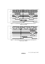
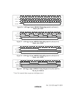
The interrupt request is triggered when the counter reaches zero, and the request is cleared by
writing 0 to the interrupt request bit TMU1R/TMU0R in TIRR. In case that the disable bit
TMU1D/TMU0D in TIDR is set, the interrupt request will be disabled. The interrupt timing
diagrams for each pre-scale clock are shown below:
Summary of Contents for HD64465
Page 25: ...Rev 3 0 03 01 page 6 of 390 ...
Page 59: ...Rev 3 0 03 01 page 40 of 390 ...
Page 97: ...Rev 3 0 03 01 page 78 of 390 ...
Page 147: ...Rev 3 0 03 01 page 128 of 390 ...
Page 199: ...Rev 3 0 03 01 page 180 of 390 ...
Page 247: ...Rev 3 0 03 01 page 228 of 390 ...
Page 385: ...Rev 3 0 03 01 page 366 of 390 ...
Page 389: ...Rev 3 0 03 01 page 370 of 390 ...
Page 409: ...Rev 3 0 03 01 page 390 of 390 ...

