Rev. 3.0, 03/01, page 160 of 390
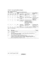
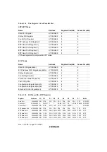
Table 12.2
Interrupt Identification Register
FIFO
Mode
Interrupt Identification
Register
Interrupt Set and Reset Functions
Bit 3
Bit 2
Bit 1
Bit 0
Priority
Level
Interrupt Type
Interrupt Source
Interrupt RESET
Control
0
X
X
1
-
None
None
-
0
1
1
0
First
Receiver Line
Status
OE, PE, FE, or BI
ULSR READ
0
1
0
0
Second
Received Data
Available
Received Data Available
URBR Read or FIFO
drops below the
trigger level
1
1
0
0
Second
Character Timer-
out Indication
No characters have been
removed from or input to
the RCVR FIFO during the
last 4 character times, and
there is at least 1 character
in it at this time.
URBR READ
0
0
1
0
Third
Transmitter
Holding Register
Empty
Transmitter Holding
Register Empty
UIIR READ if THRE
is the Interrupt
Source or THR write
0
0
0
0
Fourth
Modem Status
CTS#, DSR#, RI#, DCD#
UMSR READ
Note:
X = Not Defined
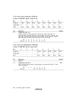
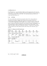
Bit
Description
Default
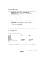
7, 6
Are set when UFCR(0)=1
-
5, 4
Always logic 0
0
3
In non-FIFO mode, this bit is a logic 0. In the FIFO mode this bit is set along with bit 2
when a time-out Interrupt is pending.
-
2, 1
Are used to identify the highest priority pending interrupt.
-
0
Is used to indicate a pending interrupt in either a hard-wired prioritized or polled
environment, with a logic 0 state. When this happens, UIIR contents may be used as a
pointer to the appropriate interrupt service routine.
-
Summary of Contents for HD64465
Page 25: ...Rev 3 0 03 01 page 6 of 390 ...
Page 59: ...Rev 3 0 03 01 page 40 of 390 ...
Page 97: ...Rev 3 0 03 01 page 78 of 390 ...
Page 147: ...Rev 3 0 03 01 page 128 of 390 ...
Page 199: ...Rev 3 0 03 01 page 180 of 390 ...
Page 247: ...Rev 3 0 03 01 page 228 of 390 ...
Page 385: ...Rev 3 0 03 01 page 366 of 390 ...
Page 389: ...Rev 3 0 03 01 page 370 of 390 ...
Page 409: ...Rev 3 0 03 01 page 390 of 390 ...

