Table of contents
Automation system
System Manual, 12/2017, A5E03461182-AE
9
6
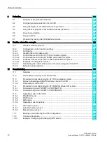
Wiring ................................................................................................................................................. 122
6.1
Rules and regulations for operation ...................................................................................... 122
6.2
Additional rules and regulations for operation of the S7-1500/ET 200MP with fail-safe
modules ................................................................................................................................ 124
6.2.1
Safe functional extra-low voltage (SELV) for fail-safe modules............................................ 124
6.2.2
Requirements of sensors and actuators for fail-safe modules ............................................. 125
6.2.3
Capacitive crosstalk of digital input/output signals ............................................................... 128
6.3
Operation on grounded infeed .............................................................................................. 128
6.4
Electrical configuration .......................................................................................................... 131
6.5
Wiring rules ........................................................................................................................... 134
6.6
Connecting the supply voltage .............................................................................................. 139
6.7
Connecting system power supply and load current supply .................................................. 140
6.8
Connecting the CPU/interface module to the load current supply ........................................ 142
6.9
Connecting interfaces for communication............................................................................. 144
6.10
Front connector for the I/O modules ..................................................................................... 145
6.10.1
Wiring front connectors for I/O modules without shield contact element .............................. 147
6.10.2
Wiring front connectors for I/O modules with shield contact element ................................... 149
6.10.3
Bringing the front connector into final position ...................................................................... 156
6.11
Marking the I/O modules ....................................................................................................... 158
6.11.1
Labeling strips ....................................................................................................................... 158
6.11.2
Optional marking ................................................................................................................... 159
7
Configuring ......................................................................................................................................... 160
7.1
Configuring the CPU ............................................................................................................. 161
7.1.1
Reading out the configuration ............................................................................................... 161
7.1.2
Address assignment ............................................................................................................. 166
7.1.2.1
Addressing - overview........................................................................................................... 166
7.1.2.2
Addressing digital modules ................................................................................................... 168
7.1.2.3
Addressing analog modules ................................................................................................. 170
7.1.3
Process images and process image partitions ..................................................................... 173
7.1.3.1
Process image - overview ..................................................................................................... 173
7.1.3.2
Assign process image partitions to an OB ............................................................................ 174
7.1.3.3
Update process image partitions in the user program .......................................................... 174
7.2
Configuring ET 200MP distributed I/O system ..................................................................... 176
7.3
Assigning PROFIsafe address to fail-safe modules with SIMATIC Safety ........................... 177
8
Basics of program execution ............................................................................................................... 178
8.1
Events and OBs .................................................................................................................... 178
8.2
CPU overload behavior ......................................................................................................... 180
8.3
Asynchronous instructions .................................................................................................... 182
Summary of Contents for Simatic S7-1500/ET 200MP
Page 1: ......


