Chapter 5
305
Programming
Data Transfer to Computer
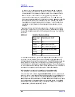
The TDF (trace data format) command is used to select measurement
or parameter units. Traces are stored internally as integers in the
range from 0 to 600, where 0 represents the bottom graticule line and
600 represents the top graticule line. Because there are 10 graticule
divisions vertically, there will be 60 measurement units per graticule.
There is a small over-range area above the top graticule line (up to 610),
so traces can contain numbers slightly larger than 600.
To convert from measurement units to parameter units or from
parameter units to measurement units, you must have the following
information at the time that the trace data is measured: log-scale
setting (dB/division or linear), reference level, and the amplitude units
in which the reference level is expressed. For log scales where the
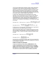
reference level is expressed in a dB-related unit, the following formulas
can be used:
If reference level is not expressed in a dB-related unit, it must first be
converted to such a unit before using the formulas.
When using a linear display scale, the following formulas can be used
with the reference level expressed in volts. If the reference level is not
expressed in volts, it must be converted to volts before these formulas
are used.
Notice that the interpretation of measurement units always depends on
the reference level and amplitude scaling of the display at the time that
the trace data was measured.
Position Units and Trace Elements
Traces are comprised of a fixed number of elements (601). Each
element has a fixed position on the horizontal axis of the trace. An
element is identified by specifying its horizontal position in position
units. Position units are integers, ranging from 1 to 601. The element
at the left end of a trace is always identified by a position value of 1.
The element at the right end of a trace has a position value of 601.
Parameter Units
Reference Level
Log Scale
Measurement Units
600
–
60
--------------------------------------------------------------
×
+
=
Measurement Units
Parameter Units
Reference Level
–
Log Scale
------------------------------------------------------------------------------------
60
600
+
×
=
Parameter Units
Reference Level
Measurement Units
600
-----------------------------------------------
×
=
Measurement Units
Parameter Units
Reference Level
---------------------------------------
600
×
=
Summary of Contents for 8560E
Page 21: ...21 1 Quick Start Guide ...
Page 48: ...48 Chapter1 Quick Start Guide Manuals Available Separately ...
Page 49: ...49 2 Making Measurements ...
Page 164: ...164 Chapter2 Making Measurements Example 13 Making Pulsed RF Measurements ...
Page 165: ...165 3 Softkey Menus ...
Page 182: ...182 Chapter3 Softkey Menus Menu Trees ...
Page 183: ...183 4 Key Function Descriptions ...
Page 228: ...228 Chapter4 Key Function Descriptions Key Descriptions Figure 4 3 CRT Alignment Pattern ...
Page 289: ...289 5 Programming ...
Page 323: ...Chapter 5 323 Programming Math Functions Figure 5 10 Display Units ...
Page 339: ...339 6 Programming Command Cross Reference ...
Page 369: ...369 7 Language Reference ...
Page 654: ...654 Chapter7 Language Reference VTL Video Trigger Level ...
Page 655: ...655 8 Options and Accessories ...
Page 665: ...665 9 If You Have a Problem ...
Page 674: ...674 Chapter9 If You Have a Problem Power Requirements Figure 9 2 AC Power Cables Available ...


