Chapter 5
311
Programming
Data Transfer to Computer
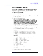
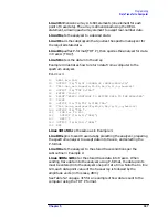
Example 7 converts binary values to measurement data and prints
them on the computer display.
E
XAMPLE
7
10
INTEGER Trace_a(1:601)
20
DIM Real_num(1:601)
30
Ref_lvl=0
!0 dBm reference level
40
Log_scale=10
!10dB/division log scale
50
OUTPUT 718;"TDF B;TRA?;"
60
ENTER 718 USING "#,W";Trace_a(*)
70
MAT Real_num= Trace_a
80
FOR X=1 TO 601
90
Real_num(X)=ReLog_scale*(Real_num(X)/60-10)
100
NEXT X
110
END
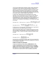
For converting linear data, use this equation:
where:
x = binary data in an array element.
RL = reference level. When RL is in volts, n will be in volts.
These equations are useful when you are interested in viewing only a
few points of data, rather than an entire trace. B-format saves time and
memory, and these equations provide a means to view the data, if
necessary.
NOTE
It is not possible to return data to the analyzer using binary format.
You must use either A-block or I-block format. These two formats are
described below.
See Table 5-2 on page 315 for an example of how data is sent to the
computer using the TDF B format.
TDF A (A-block format): Return Absolute Block-Data Fields in
Measurement Units
The A-block format transmits data in measurement units as binary
numbers in an absolute block-data field, or field of a known size, similar
to the binary format. Each data point is sent as two 8-bit bytes; the
most significant byte is sent first, followed by the least significant byte.
The A-block format also transfers a four-byte header before the 601
points of trace data. The bytes are the ASCII characters "#", "A", and a
two-byte length field specifying the number of data bytes in the block
that follows (that is, 1202).
n
RL
x
600
---------
×
=
Summary of Contents for 8560E
Page 21: ...21 1 Quick Start Guide ...
Page 48: ...48 Chapter1 Quick Start Guide Manuals Available Separately ...
Page 49: ...49 2 Making Measurements ...
Page 164: ...164 Chapter2 Making Measurements Example 13 Making Pulsed RF Measurements ...
Page 165: ...165 3 Softkey Menus ...
Page 182: ...182 Chapter3 Softkey Menus Menu Trees ...
Page 183: ...183 4 Key Function Descriptions ...
Page 228: ...228 Chapter4 Key Function Descriptions Key Descriptions Figure 4 3 CRT Alignment Pattern ...
Page 289: ...289 5 Programming ...
Page 323: ...Chapter 5 323 Programming Math Functions Figure 5 10 Display Units ...
Page 339: ...339 6 Programming Command Cross Reference ...
Page 369: ...369 7 Language Reference ...
Page 654: ...654 Chapter7 Language Reference VTL Video Trigger Level ...
Page 655: ...655 8 Options and Accessories ...
Page 665: ...665 9 If You Have a Problem ...
Page 674: ...674 Chapter9 If You Have a Problem Power Requirements Figure 9 2 AC Power Cables Available ...

